Actuator for control loading system

a technology of actuators and loading systems, applied in the field of actuators, can solve the problems of accurately adjusting the control force, unwanted force being applied to the motors, backlash, etc., and achieve the effect of accurately determining the magnitude of the force and being easy to mount and manufacture compactly

Active Publication Date: 2014-06-10
BAROTECH SYNERGY
View PDF14 Cites 6 Cited by
  • Summary
  • Abstract
  • Description
  • Claims
  • Application Information

AI Technical Summary

Problems solved by technology

However, with a complicated configuration of the mechanical means of linking control sticks with the motor, the said existing techniques are complicated with the installation structure and cannot keep the motors horizontal, which brings about an unwanted force being applied to the motors by the weight of the control sticks or the means of linking.
This problem keeps one from accurately adjusting the control force when manipulating the motors to apply the control force.
Meaning that if one pair of gears engages configuring the reducer, a backlash would occur in between the gaps, and the pulley would around a belt becomes loose after extended use and would spin with no traction.
In addition, Korea Public Patent No. 10-2004-0092108 is unaffected from the said problem because it connects the motor directly with the axis of rotation, but the because of the limits to the mounting structure of the motor it can only be applied to the virtual simulation system of limited application.
Also, the above existing techniques use the rotor of the rotation angle by sensing the location sensor or sensing the rotation angle by the built-in encoder, however, in order to set the absolute reference point only with a single position sensor, they should bear start-up time delay and inconvenience in that start-up time needs to be established with software whenever the virtual simulation system is turned on.
And though it is desirable to determine the magnitude of the force applied to an actuator as the control stick is manipulated so as to calculate the control force corresponding to the movement of the control stick, the said preceding arts do not include any force sensors and if one can be accommodated, the installation location is not proper and the magnitude of the force cannot be measured accurately because of their structure.

Method used


Image

  • Actuator for control loading system
  • Actuator for control loading system
  • Actuator for control loading system

Examples


Embodiment Construction

[0029]Below, desirable embodiments of the present invention will be described in detail with reference to the attached figures so that those who have common knowledge of the relevant field can implement it easily. In the attached figures, caution should be taken so that as much as possible the same the reference numbers used for configuration or operation also be used when marking the configuration or operations in other figures. In addition, in a case where a detailed account of relevant publicly known function or configuration may unnecessarily obscure the gist of the present invention unnecessarily, such a detailed account will be omitted.

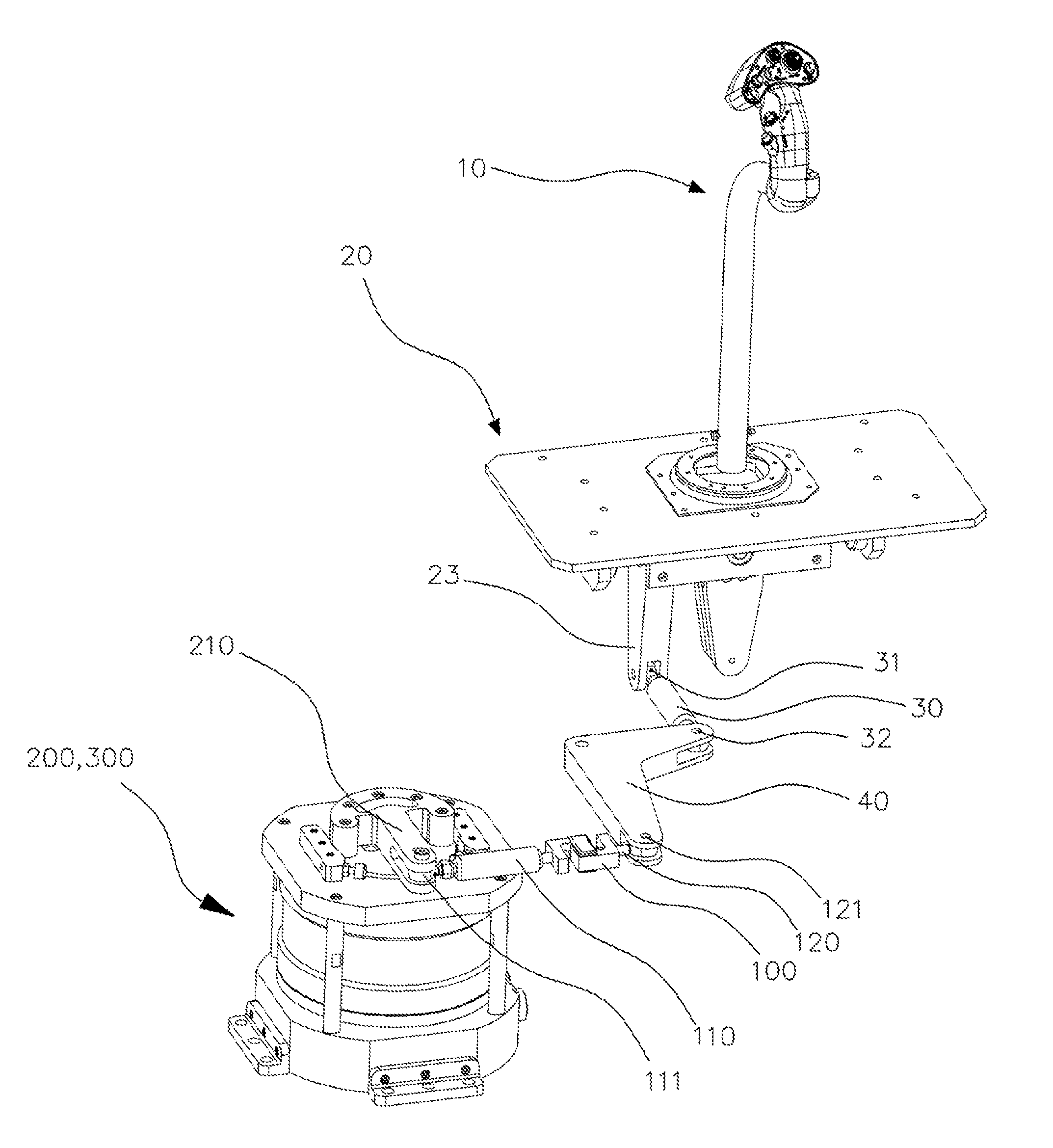
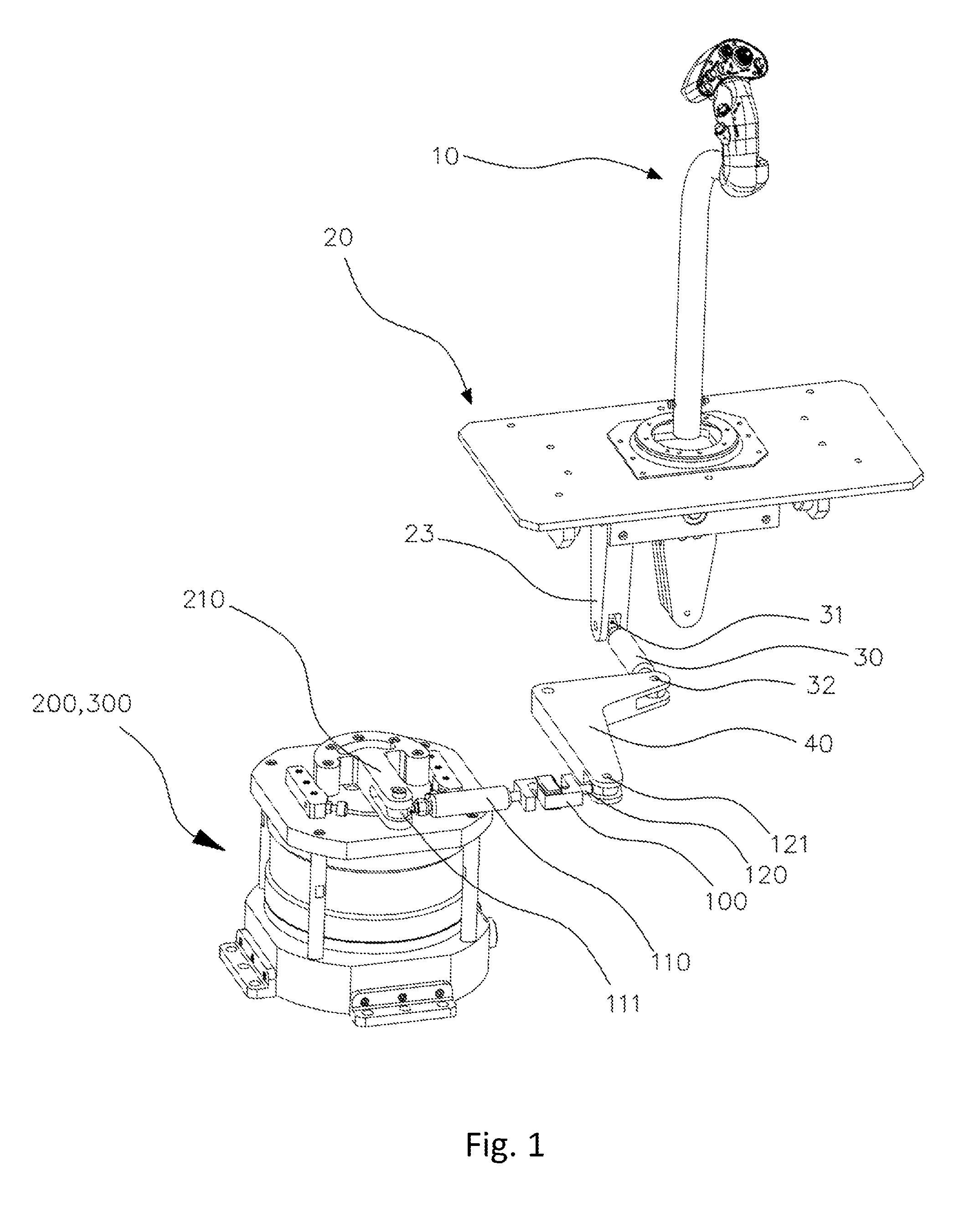
[0030]FIG. 1 is an oblique view from above the actuator for the control loading system according to the embodiment of the present invention, which is connected to the control stick (10).

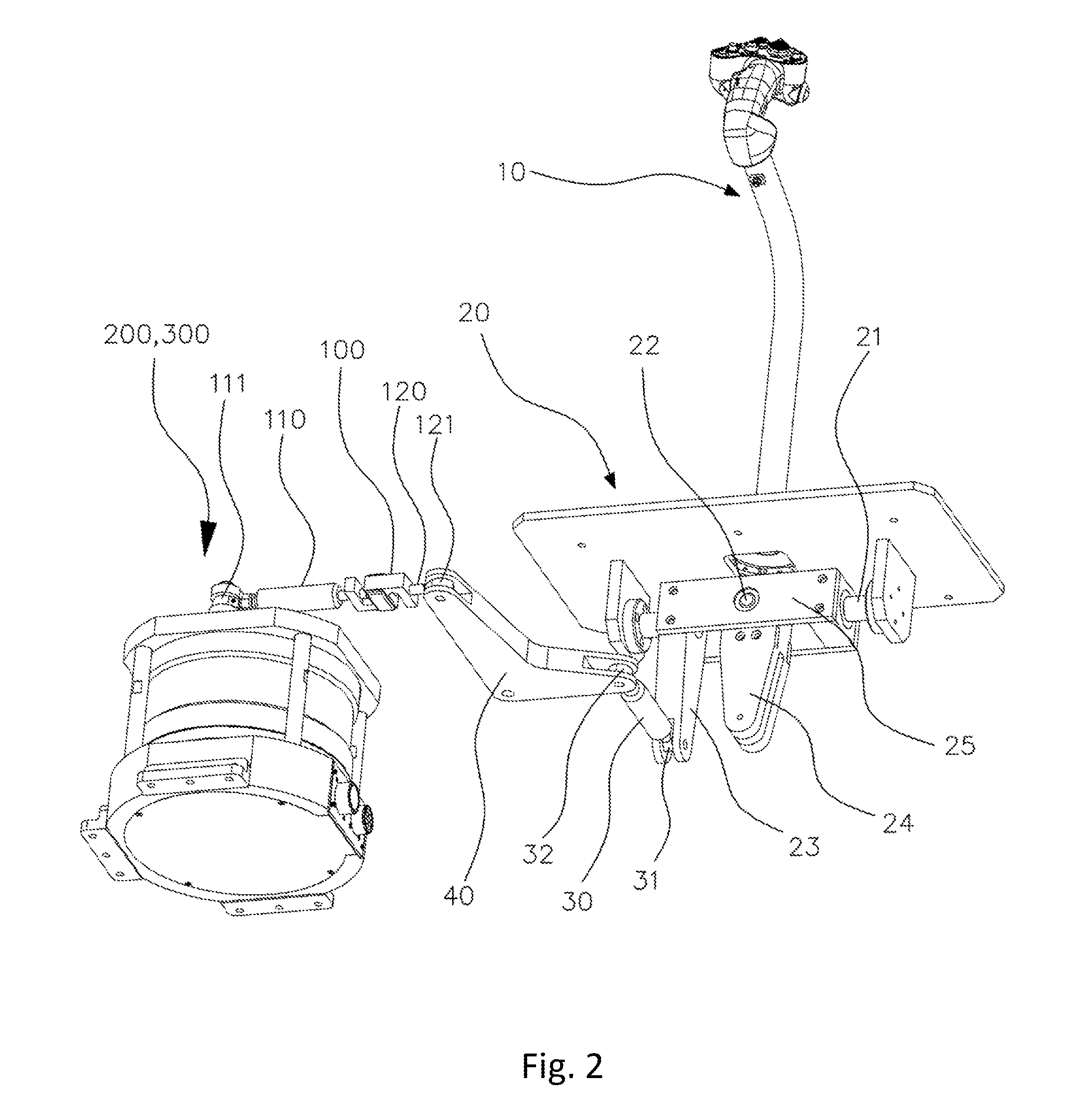
[0031]FIG. 2 is an oblique view from below the actuator for the control loading system according to the embodiment of the present invention, which is connected t...


PUM


Abstract

An actuator which can be installed in a system for the virtual simulation of aircraft, ships and vehicles to help the system with the controls. More specifically, the invention is an actuator used for a control loading system, which can be installed into a virtual simulation system, receive force delivered by the movement of a control stick laterally while measuring the applied force. It can connect a lever which delivers the control force equivalent to the applied force and reaction force by making use of a direct drive motor, including a potentiometer which senses the angle of rotation while sensing the initial reference position separately from an encoder, limiting the rotation range of the rotating lever, fixing the initial neutral position, and the control loading system for actuators manufactured compactly on the whole.

Description

TECHNICAL FIELD[0001]This invention is an actuator which can be installed in a system for the virtual simulation of aircraft, ships and vehicles help the system with the controls. More specifically, the invention is an actuator used for a control loading system, which can be installed into a virtual simulation system; receive force delivered by the movement of a control stick laterally while measuring the applied force. It can connect a lever which delivers the control force equivalent to the applied force and reaction force by making use of a direct drive motor, including a potentiometer which senses the angle of rotation while sensing the initial reference position separately from an encoder, limiting the rotation range of the rotating lever, fixing the initial neutral position, and the control loading system for actuators manufactured compactly on the whole.BACKGROUND OF TECHNOLOGY[0002]Virtual simulation system is commonly used for the training of aircraft, ship, vehicle or othe...

Claims


Application Information

Patent Timeline
Patent Type & Authority Patents(United States)
IPC IPC(8): B64C13/04B64C13/24G09B9/28G09B9/08
CPCG09B9/28Y10T74/20396
Inventor KOO, CHIL, HYO
Owner BAROTECH SYNERGY
Why Eureka
Try Eureka