Suspension mounting structure for vehicle

a suspension and mounting structure technology, applied in the direction of roofs, transportation and packaging, vehicle arrangements, etc., can solve the problems of increasing the weight of the vehicle body, the inability to utilize the front side frames proactively, etc., to ensure the rigidity of supporting loads, simplify the structure of each sub frame, and quiet the effect of the vehicle interior

Active Publication Date: 2014-06-10
MAZDA MOTOR CORP
View PDF24 Cites 15 Cited by
  • Summary
  • Abstract
  • Description
  • Claims
  • Application Information

AI Technical Summary

Benefits of technology

[0006]The present invention was contrived in view of the points described above, and an object thereof is to provide a suspension mounting structure for a vehicle, which is capable of effectively ensuring the rigidity of supporting a front suspension by using a simple configuration without increasing the weight of a vehicle body.
[0008]In the present invention according to the configuration described above, the rear parts of the sub frames are provided with the pair of right and left lower arm supporting parts for swingably and elastically displaceably supporting the lower arms of the front suspension, the pair of right and left first fixing parts that rigidly bond the rear end part of the rear sub cross member to the bottom surface of the vehicle body, and the pair of right and left second fixing parts that rigidly bond the side end parts of the rear sub cross member to the bottom surface of the vehicle body at the positions that are offset outward from the first fixing parts in the vehicle width direction. Therefore, thrust loads that are input from the lower arms of the front suspension to the rear parts of the sub frames can be effectively supported by both the sub frames and the bottom surface of the vehicle body.
[0009]Thus, unlike a conventional device in which a rubber bush is disposed in a supporting part that supports a side end part of a sub frame supporting the front suspension in order to absorb road noise that is input from a wheel to the front suspension when the vehicle runs, the suspension mounting structure of the present invention is advantageous in simplifying the structure of each sub frame to attain a light vehicle body and adequately ensuring the rigidity of supporting the loads that are input from the tires to the front suspension when the vehicle turns. In addition, since the lower arm supporting parts provided in the rear parts of the sub frames swingably and elastically displaceably support the lower arms of the front suspension, road noise that is input to the lower arms can be absorbed by the lower arm supporting parts and effectively prevented from being transmitted to the sub frames and the front side frames supporting the sub frames. As a result, a sufficiently quiet vehicle interior can be ensured.

Problems solved by technology

However, the front side frames cannot be utilized proactively as supporting members for supporting loads that are input from the tires to the front suspension when the vehicle turns.
In this case, sufficient strength of the sub frames needs to be ensured in order to apply the loads stably, which inevitably leads to an increase in the weight of the vehicle body.

Method used


Image

  • Suspension mounting structure for vehicle
  • Suspension mounting structure for vehicle
  • Suspension mounting structure for vehicle

Examples


Embodiment Construction

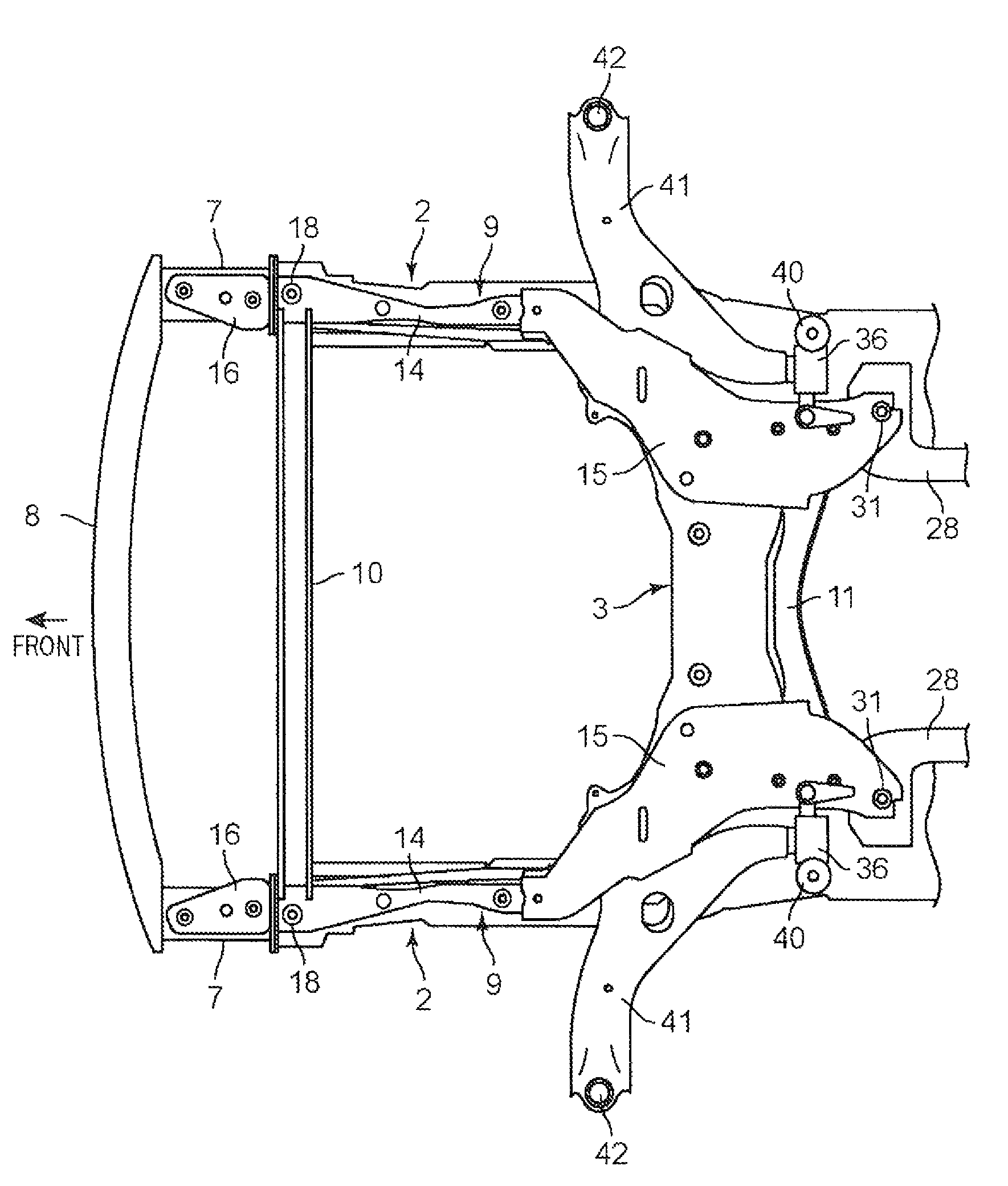
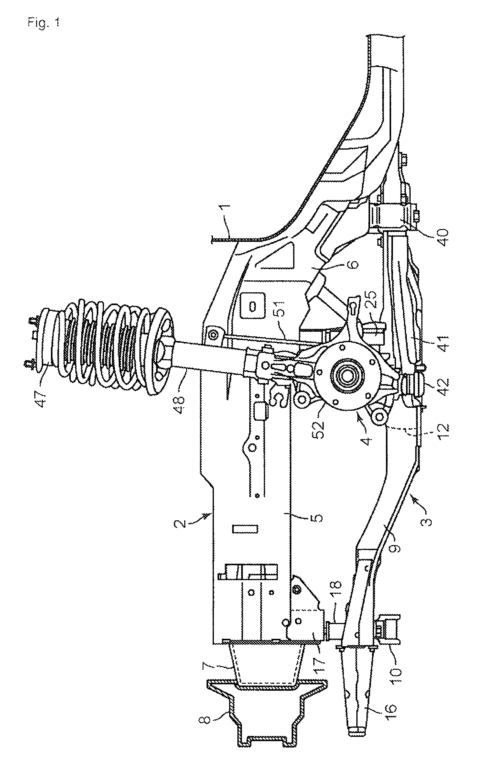
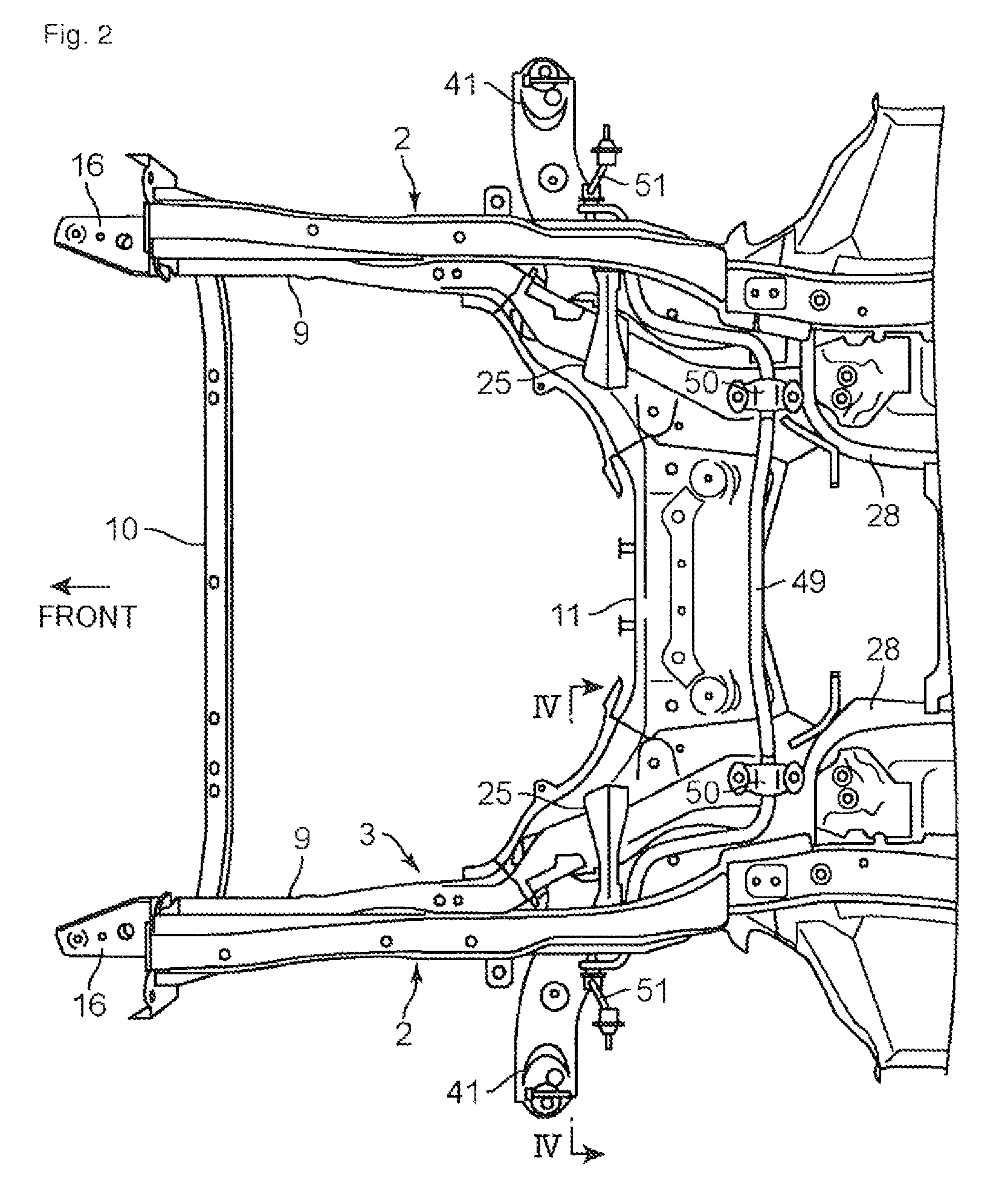
[0021]FIGS. 1 to 4 each show an embodiment of a suspension mounting structure for a vehicle according to the present invention. The suspension mounting structure for a vehicle has a pair of right and left front side frames 2 that extend from a dash panel 1 installed in a front surface part of a vehicle interior toward the front side of the vehicle, and sub frames 3 provided below the front side frames 2. A front suspension 4 is supported on the sub frames 3.

[0022]Each of the front side frames 2 is configured to have a closed cross-sectional shape with an inner panel 2a located in an inner side in a vehicle width direction and an outer panel 2b located on an outside side in the vehicle width direction (see FIG. 4), and has a horizontal part 5 extending substantially horizontally as viewed from the side, and a kick up part 6 that extends rearward from a rear end part of the horizontal part 5 while inclining downward (with a front side up) along a lower end part of the dash panel 1 (se...


PUM


Abstract

An object of the present invention is to effectively ensure the rigidity of supporting a front suspension with a simple configuration, without increasing the weight of a vehicle body.In a suspension mounting structure for a vehicle in which a front suspension is supported by sub frames 3, the sub frames 3 have a pair of right and left side sub frames 9 that extend in a front-rear direction of a vehicle in lower parts of front side frames 2; and a rear sub cross member 11 that couples rear end parts of the right and left side frames 9 to each other. Rear parts of the sub frames 9 are provided with: lower arm supporting parts for swingably and elastically displaceably supporting lower arms 41 of the front suspension; first fixing parts 31 that rigidly bond a rear end part of the rear sub cross member 11 to a bottom surface of a vehicle body; and second fixing parts 40 that rigidly bond side end parts of the rear sub cross member 11 to the bottom surface of the vehicle body at positions that are offset outward from the first fixing parts 31 in a vehicle width direction.

Description

TECHNICAL FIELD[0001]The present invention relates to a suspension mounting structure for a vehicle, which has a pair of right and left front side frames that extend from a dash panel installed in a front surface part of a vehicle interior toward the front side of a vehicle, and sub frames provided below the front side frames, to support a front suspension on the sub frames.BACKGROUND ART[0002]Patent Document 1 below discloses a conventional vehicle body structure in which side sub frames (side frames) are provided below a pair of right and left front side frames (vehicle body frames) extending in a front-rear direction of a vehicle, and the side sub frames are supported elastically displaceably on the front side frames via supporting parts having rubber bushes. This vehicle body structure is provided with a pair of right and left impact absorbing members extending forward beyond front end parts of the side sub frames, and a reinforcement that extends in a vehicle width direction so...

Claims


Application Information

Patent Timeline
Patent Type & Authority Patents(United States)
IPC IPC(8): B60G7/02B62D21/11
CPCB60G2204/15B60G7/02B60G2206/60B62D21/11B60G2204/14
Inventor OTANI, TAKAHIROFUKUSHIMA, MASANOBUTAKESHITA, HIROAKI
Owner MAZDA MOTOR CORP
Why Eureka
Try Eureka