
Non-intrusive method for detection of chemical elements

a detection method and chemical element technology, applied in the direction of material analysis using wave/particle radiation, x/gamma/cosmic radiation measurement, instruments, etc., can solve the problems of large safety risks, inability to detect capture radiation optimal signal-to-noise ratio, and relatively long total duration of detection operation

Inactive Publication Date: 2014-06-10
COMMISSARIAT A LENERGIE ATOMIQUE ET AUX ENERGIES ALTERNATIVES
View PDF6 Cites 3 Cited by
  • Summary
  • Abstract
  • Description
  • Claims
  • Application Information

AI Technical Summary

Benefits of technology

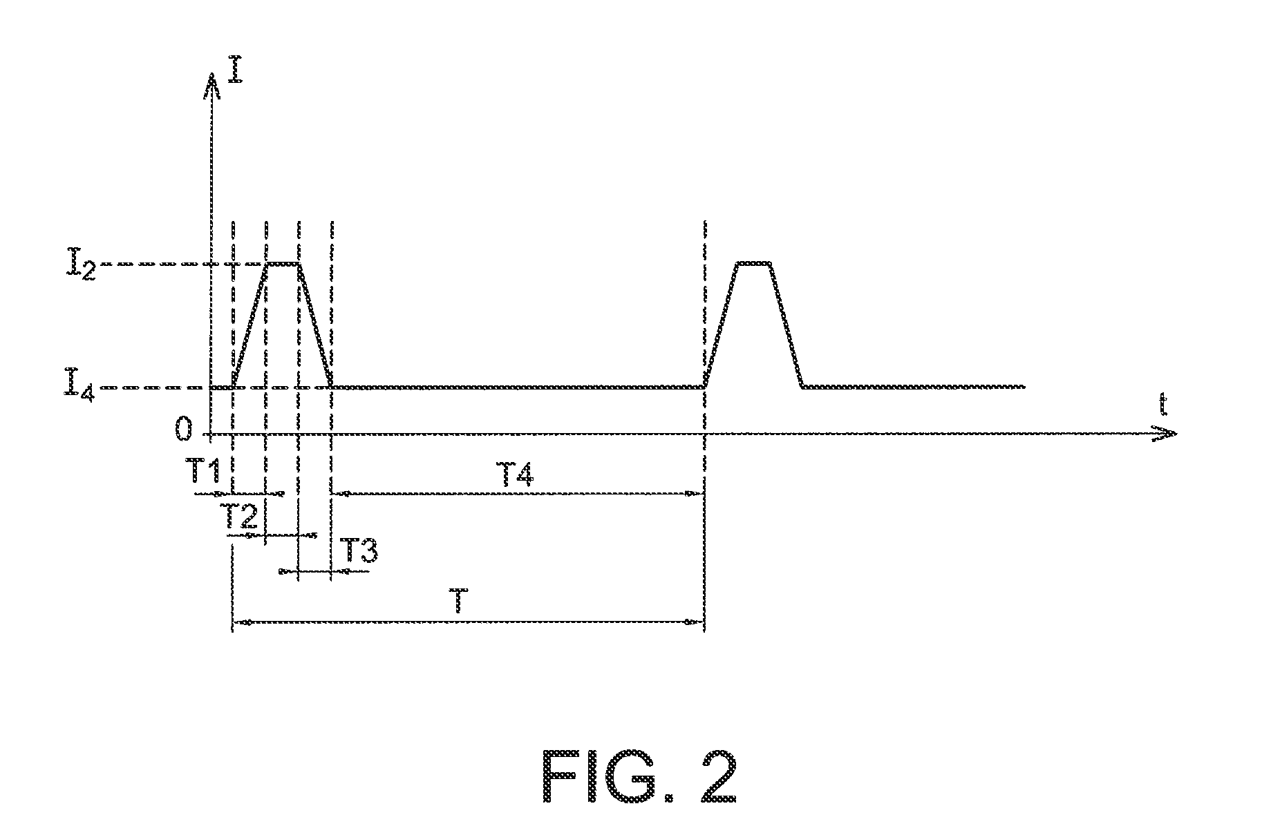
[0033]With the detection system of the invention it is advantageously possible to use a large proportion of period T of the neutron pulses (typically 95%) to detect simultaneously both types of radiation induced by the thermal neutrons (capture) and by the fast neutrons (inelastic scattering and reactions (n,α), (n,p), etc.)

Problems solved by technology

However, since the emission of the TPA is continuous it follows that, with this method, detection of the capture radiation is not optimal in signal-to-noise ratio terms.
One problem lies in the fact that neither of the two methods, one based on the pulsed tube, the other on TPA, enables the capture radiation and the inelastic radiation to be detected simultaneously with the best possible sensitivity, and consequently all the elements sought to be identified satisfactorily.
The total duration of a detection operation is consequently relatively long, representing a major disadvantage in terms of safety.
A simultaneous use of an associated particle neutron generator G1 which emits neutrons continuously and of a pulsed neutron generator G2 which emits neutron pulses apparently has a disadvantage for the detection of capture radiation due to the presence of a residual neutron emission between the pulses of generator G2, this residual emission being due to the continuous emission of generator G1.

Method used


Image

  • Non-intrusive method for detection of chemical elements
  • Non-intrusive method for detection of chemical elements
  • Non-intrusive method for detection of chemical elements

Examples


Embodiment Construction

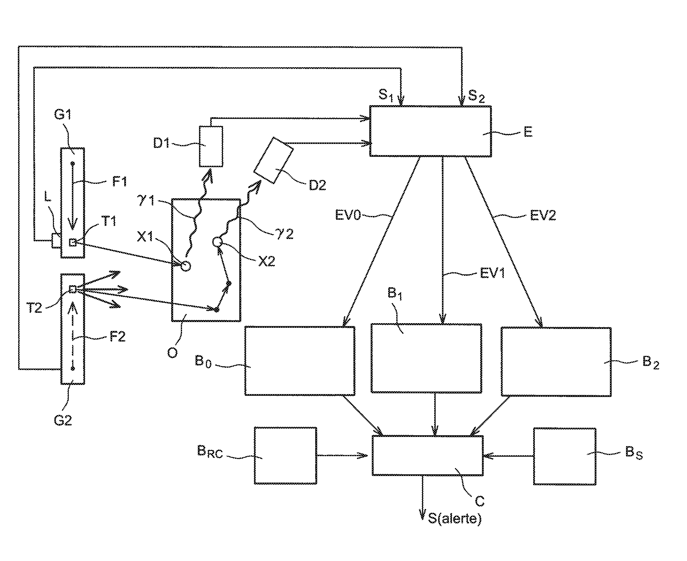
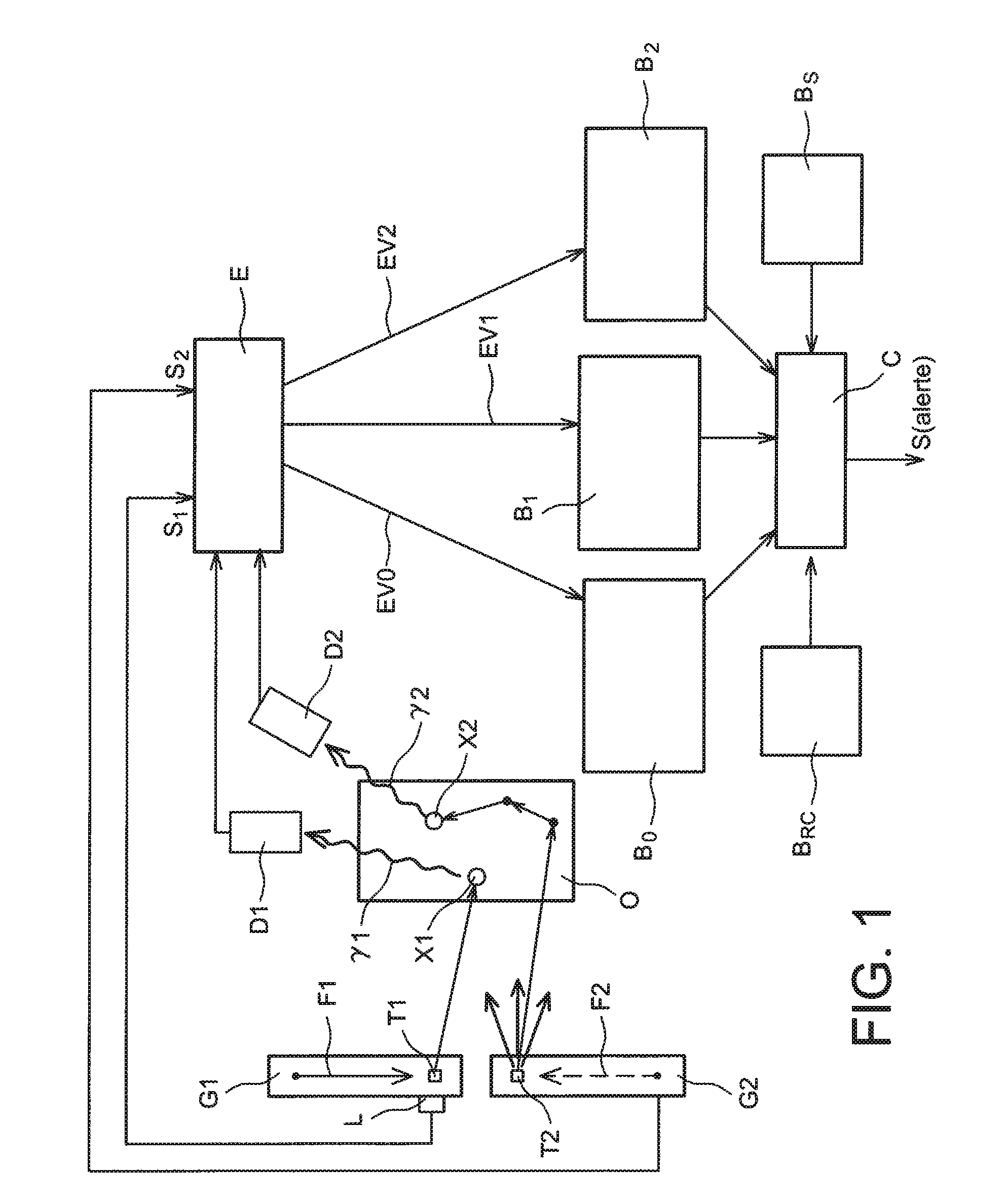
[0042]FIG. 1 represents a schematic diagram of a non-intrusive detection system which uses the method of the invention.

[0043]Around object O which may contain chemical elements to be detected, the detection system of the invention includes an associated particle neutron generator G1, a pulsed neutron generator G2, two detectors D1 and D2, an electronic processing circuit E which processes and shapes the signals originating from the detectors D1 and D2, databases Bo, B1, B2 which store the data delivered by the electronic processing circuit E, reference databases BRC and Bs which store, respectively, data relative to the reference capture lines and to inelastic gamma radiation reference spectra, and a computer C which calculates a signal which reveals the presence or absence of chemical element(s) or dangerous products on the basis of the data contained in the databases B0, B1, B2, BRC and BS.

[0044]The neutron generators G1 and G2 emit neutrons some of which are directed towards the ...


PUM

PropertyMeasurementUnit
weightaaaaaaaaaa
weightsaaaaaaaaaa
TMaaaaaaaaaa

Abstract

A method for detecting the presence of a chemical element in an object by emission of neutrons onto the object, characterized in that the emission of neutrons onto the object is constituted, firstly, by a continuous emission of neutrons originating from an associated particle neutron generator (G1) and, secondly, by an emission of neutron pulses which are superimposed on the continuous emission of neutrons, where the neutron pulses originate from a pulsed neutron generator (G2) which generates neutron pulses of pulse duration T2, where two successive neutron pulses are separated by a duration T4, and where the continuous and pulsed emissions of neutrons on to the object produce a gamma capture radiation and an inelastic gamma radiation.

Description

CROSS REFERENCE TO RELATED APPLICATIONS OR PRIORITY CLAIM[0001]This application is a National Phase of PCT / EP2009 / 067102, filed Dec. 14, 2009, entitled, “METHOD FOR THE NON-INTRUSIVE DETECTION OF A CHEMICAL ELEMENT”, and which claims priority of, French Patent Application No. 08 58564, filed Dec. 15, 2008, the contents of which are incorporated herein by reference in their entirety.TECHNICAL FIELD AND PRIOR ART[0002]The invention concerns a non-intrusive method for detection of at least one chemical element present in a liquid or a solid.[0003]The invention applies, for example, to the detection of an explosive (or explosives), a chemical weapon (or weapons) or a drug (or drugs) in the field of civil security (luggage inspection, freight containers, etc.), to the search for contraband products (customs inspections), to mine clearance (civil security and military applications), and again to the characterisation of materials constituting radioactive waste produced by the nuclear indus...

Claims


Application Information

Patent Timeline
Patent Type & Authority Patents(United States)
IPC IPC(8): G01N23/222G01N23/202
CPCG01N23/222G01V5/00G01N23/202G01N23/00G01V5/0008
Inventor CARASCO, CEDRICPEROT, BERTRAND
Owner COMMISSARIAT A LENERGIE ATOMIQUE ET AUX ENERGIES ALTERNATIVES
Learn More