Gap seal for gun

a gap seal and gun technology, applied in the field of guns, can solve the problems of lead pieces, burns, safety hazards, etc., and achieve the effects of eliminating burns, improving the safety and comfort of the revolver, and reducing the risk of accidental damag

Active Publication Date: 2014-06-17
KUNAU DANIEL
View PDF12 Cites 1 Cited by
  • Summary
  • Abstract
  • Description
  • Claims
  • Application Information

AI Technical Summary

Benefits of technology

This patent aims to improve the safety and comfort of revolvers by closing the gap between the barrel and cylinder, preventing burns and reducing noise. It also looks to better complete combustion and increase efficiency of the bullet, as well as better utilizing a longer barrel and making revolver carbines safer and more effective. The invention also includes reducing manufacturing costs by using a sliding sleeve to close the gap between the barrel and cylinder. Overall, the patent looks to enhance the performance and practicality of revolvers through various technical improvements.

Problems solved by technology

Most all of these disadvantages relate to the revolver gap, or the gap between the barrel and the revolving cylinder, or more particularly the gap between the barrel and the front of the chamber in the revolving cylinder which is aligned with the barrel.
Unlike other firearms where the cartridges—each comprising a shell, filled with gun powder, and topped with a bullet, are individually and successively positioned within a firing chamber attached to the barrel; it has generally been accepted that the revolver gap is an inherent weakness in a revolver, necessitated by the need to provide clearance between the revolving cylinder and the barrel.
Probably the biggest disadvantage associated with the revolver gap is safety.
People have been injured by lead pieces and burned by flame gases escaping through the gap.

Method used


Image

  • Gap seal for gun
  • Gap seal for gun
  • Gap seal for gun

Examples


Embodiment Construction

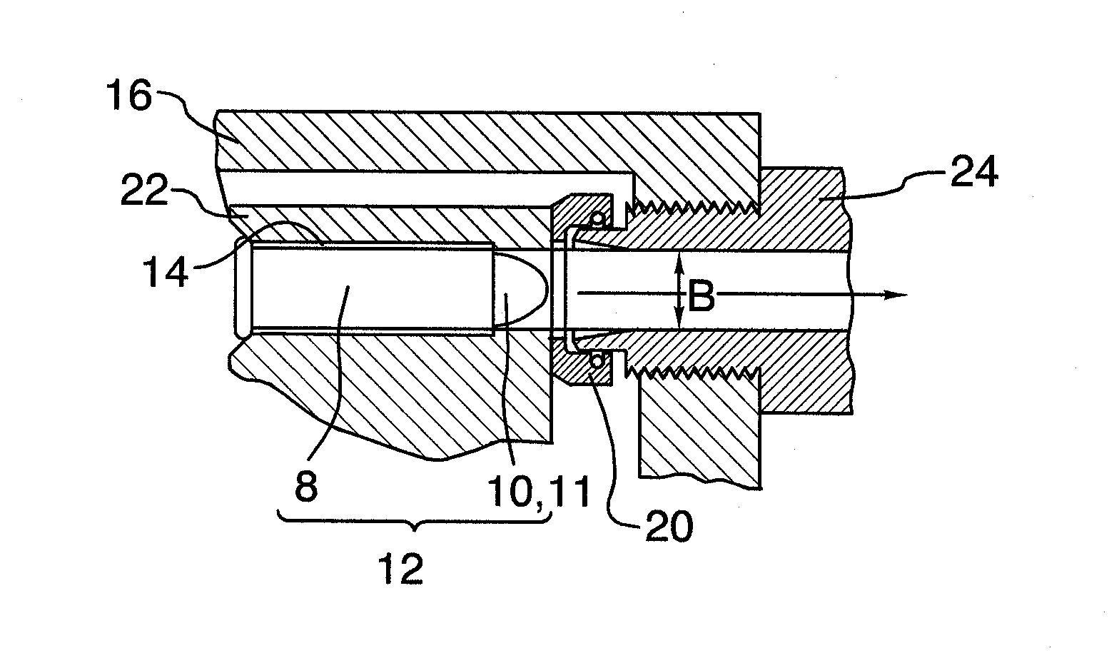
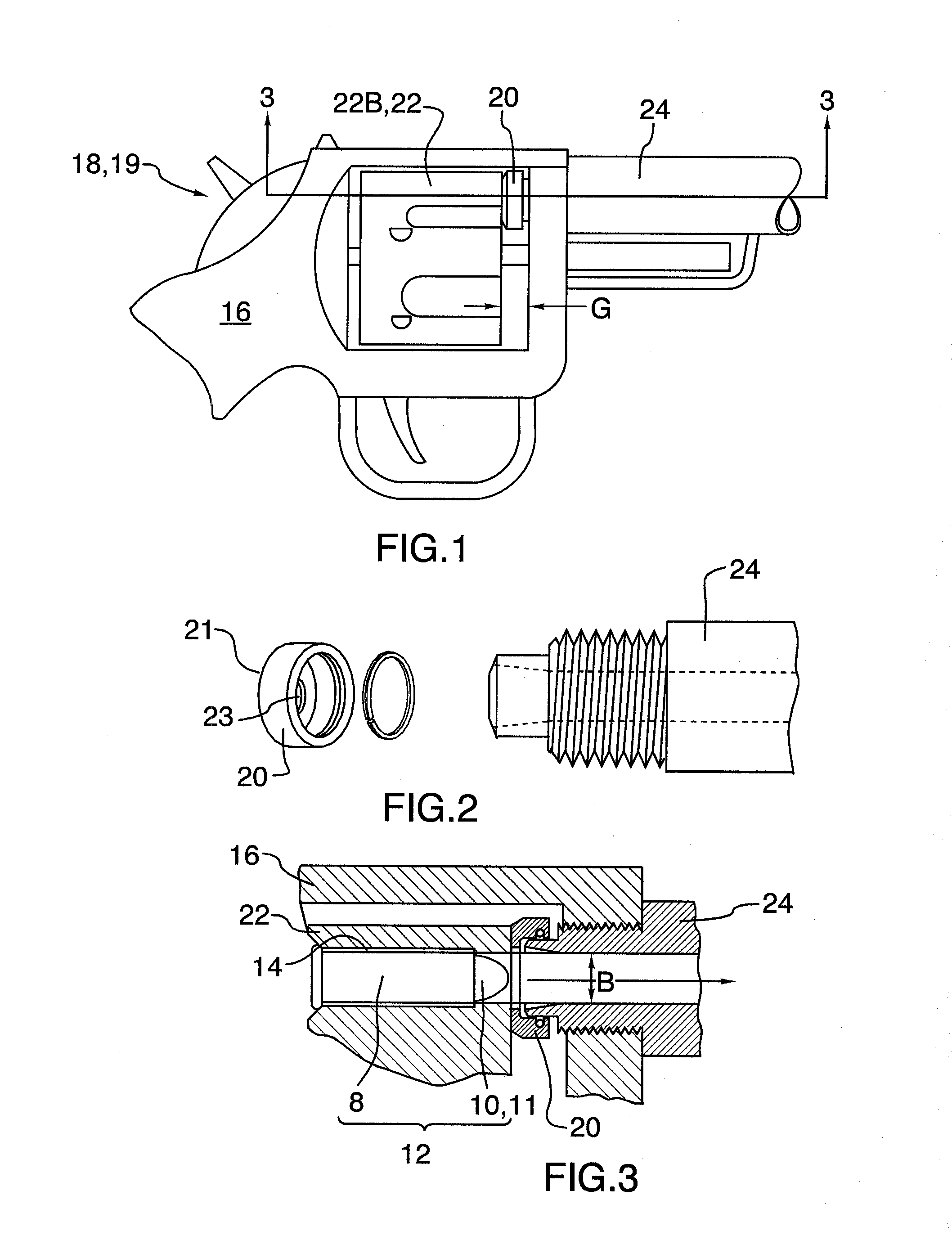
[0017]Turning now to the drawings, and more particularly to FIG. 1, we have a perspective view of a a revolver 18 having a gap seal positioned over a diametrically reduced rear portion of the barrel 24 in front of the revolving cylinder 22. FIG. 2 is a perspective exploded view of a rear portion of the barrel and the gap seal shown in FIG. 1. In a revolver having a frame 16, carrying a barrel 24 and a revolving cylinder 22 having multiple cartridge chambers 14 therearound, each configured to hold and sequentially and longitudinally align a cartridge 12 therein carrying a bullet 10, and shell 8, with a rear portion of the barrel 24, the improvement most broadly comprises: a) a sliding sleeve 20 positioned over an inner end portion of the barrel 24, said end portion of the barrel 24 and inner diameter of the sliding sleeve 20 closely mated; and, b) said sliding sleeve 20 having a front face 21 having a central opening 23 therethrough having an inner diameter nominally equivalent to ma...


PUM


Abstract

A gun or other projectile launching device includes a frame, and a barrel, including a bore therethrough, held in position by the frame. A cylinder is rotatable attached to the frame in close proximity to an inner end portion of the barrel, the cylinder having multiple chambers and configured to sequentially and longitudinally align a chamber with the bore of the barrel. A sleeve is slidingly positioned over the inner end portion of the barrel. The sleeve has a front face with a central opening therethrough, that has a size less than an inner diameter of the sleeve, but no smaller than a diameter of the bore through the barrel. The sleeve is configured to slide back, substantially in response to gas pressure, until the front face of the sleeve is forcibly maintained in contact with the cylinder to eliminate a gap between the cylinder and the barrel.

Description

CROSS-REFERENCE TO RELATED APPLICATIONS[0001]This application is a continuation of U.S. patent application Ser. No. 13 / 155,743 entitled “REVOLVER CYLINDER GAP SEAL” filed on Jun. 8, 2011, the entire contents of which are hereby incorporated by reference.FIELD OF THE INVENTION[0002]This invention relates to guns which have a gap between the feed mechanism and the barrel. More particularly this invention relates to sealing the gap between the chamber of the feed mechanism that is aligned with the barrel, and the barrel, to enhance safety, as well as to contain energy loss and enhance bullet velocity.BACKGROUND OF THE INVENTION[0003]A revolver is the least expensive, shortest, lightest and most reliable multi-shot action gun available. Revolvers however do have their disadvantages. Most all of these disadvantages relate to the revolver gap, or the gap between the barrel and the revolving cylinder, or more particularly the gap between the barrel and the front of the chamber in the revol...

Claims


Application Information

Patent Timeline
Patent Type & Authority Patents(United States)
IPC IPC(8): F41C3/14F41A3/76
CPCF41C3/14F41A3/76
Inventor KUNAU, DANIEL
Owner KUNAU DANIEL
Why Eureka
Try Eureka