Wiping device for an ink jet franking machine

a technology of ink jet franking machine and cleaning device, which is applied in the field of mail handling, can solve the problems of not preventing the print head and its environment as well to get dirtier and dirtier, and achieve the effects of improving the cleaning of the print head, simple and efficient, and efficient and periodic cleaning

Active Publication Date: 2014-06-17
NEOPOST TECH SA
View PDF11 Cites 5 Cited by
  • Summary
  • Abstract
  • Description
  • Claims
  • Application Information

AI Technical Summary

Benefits of technology

[0008]Considering that the quality of the printed postage indicia is of utmost importance as the imprint represents a monetary value, and a critical data element to be scanned, it is therefore an object of the invention to propose a wiping device for efficiently and periodically cleaning the ink jet nozzles of the print head of a franking machine. Another object of the invention is to provide such a device that mainly aims at improving the cleaning of the print heads with a wiping device which is as simple and efficient as possible. Another object of the invention is to provide such a device that remains efficient and clean over a long operating period.
[0014]The use of this kind of cleaning fluid really improves the efficiency of the wiping for limiting the pollution of the print heads and their environment.
[0016]The wiping of the ejection nozzles becomes even more efficient as the cleaning rollers are themselves maintained as clean as possible.

Problems solved by technology

Though the cleaning devices disclosed above could prove rather satisfactory under standard operating conditions, they do not prevent the print heads and their environment as well to get dirtier and dirtier with the unavoidable accumulation of ink particles over time or under industrial conditions.

Method used


Image

  • Wiping device for an ink jet franking machine
  • Wiping device for an ink jet franking machine
  • Wiping device for an ink jet franking machine

Examples


Embodiment Construction

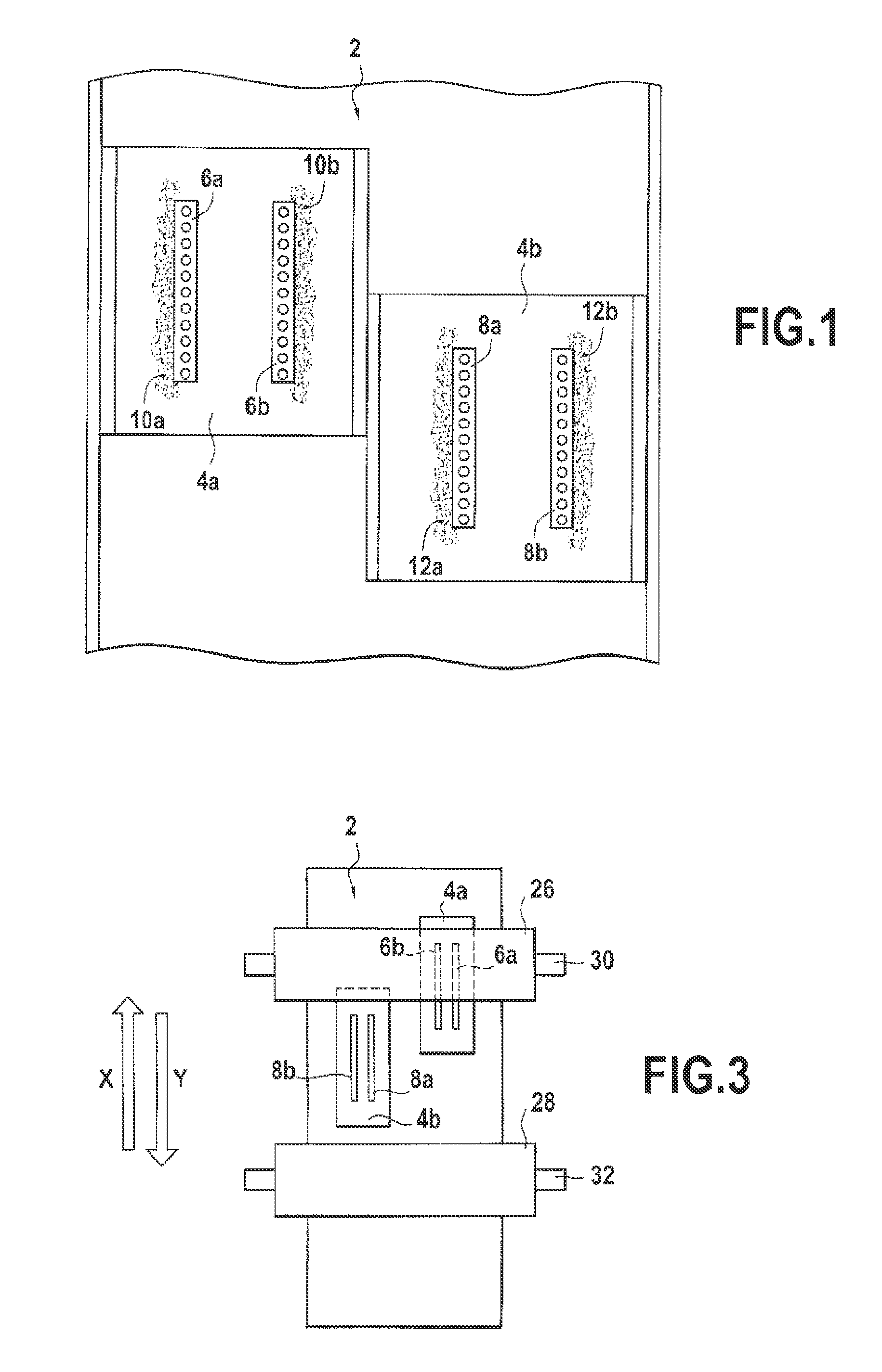
[0024]Referring to FIG. 1, a standard printing module 2 mounted on a franking machine (illustrated on FIG. 2 by its base 3 only) comprises two print heads 4a, 4b with for example their two rows 6a, 6b, 8a, 8b of ink ejections nozzles. After a multiplicity of wiping operations along the moving directions X, Y between extreme printing and capping positions, ink particles significantly pollute the print heads 4a, 4b and the wipers themselves as well which cannot remove all the ink. Ink deposits 10a, 10b, 12a, 12b are thus formed alongside the rows of nozzles. At the same time, ink particles that are projected all over the spitting and wiping areas, progressively pollute the inside of the franking machine that becomes dirtier and dirtier with other ink deposits.

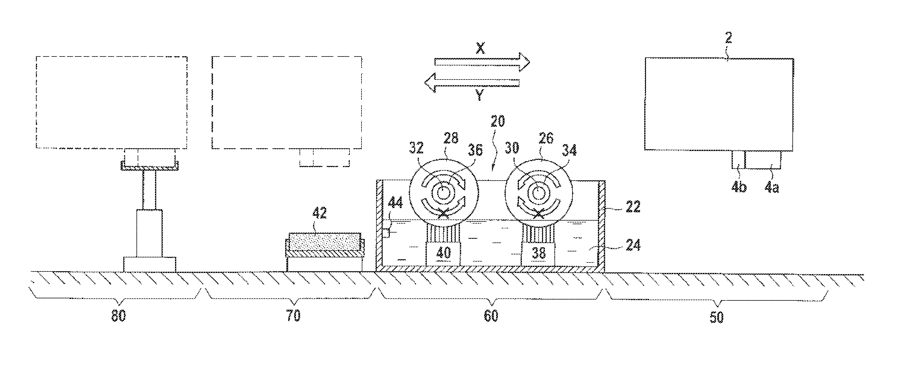
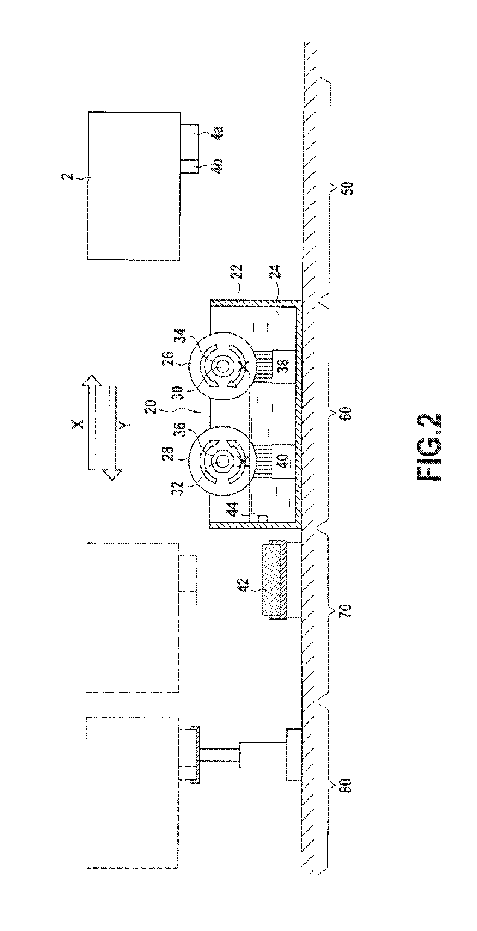
[0025]FIG. 2 illustrates schematically the combination of the printing module 2 and a wiping device 20 according to the invention. This wiping device first comprises a container 22 filled of a cleaning fluid 24 made of a polyethe...


PUM


Abstract

A wiping device (20) for cleaning outer surfaces of at least one row of ejection nozzles in at least one print head (4a, 4b) of an ink jet printing module (2) of a franking machine when the module is moving above the wiping device in first and second directions (X, Y), comprising two wiping rollers (26, 28) located one behind the other in the first direction and adapted to rotate in opposite directions around respective fixed shafts (30, 32), the two wiping rollers being permanently dampened in contact with a cleaning fluid (24) contained inside a container (22); and the two wiping rollers are adapted via a one-way bearing (34, 36) to remain stationary alternatively, one during the moving of the module in the first direction and the other during the moving of the module in the second direction.

Description

FIELD OF THE INVENTION[0001]The present invention relates to the field of mail handling, and more particularly to a cleaning device of a franking machine that intermittently wipes the ejection surfaces of the ink jet nozzles of a print head.BACKGROUND OF THE INVENTION[0002]Service stations are known in the field of ink jet franking machines for cleaning and capping a print head at a location beyond a printing station. In intervals between printing operations, the print head is moved beyond the printing station into the service station to be wiped or capped or both.[0003]Generally the service station comprises a carriage that is movable transversally to the print head's path so as to bring the wiping device or the capping apparatus into engagement with the print head.[0004]In U.S. Pat. No. 5,880,755 is disclosed a cleaning device for cleaning the outer surfaces of a row of ejection nozzles integrated in at least one print module of an ink jet print head of a postage meter having a ba...

Claims


Application Information

Patent Timeline
Patent Type & Authority Patents(United States)
IPC IPC(8): B41J2/165
CPCB41J2/16535G07B2017/00532B41J2/16538B41J2/16552
Inventor BERNARD, DOMINIQUE
Owner NEOPOST TECH SA
Why Eureka
Try Eureka