
Adjustable optical lens

a technology of optical lenses and adjustment points, applied in the field of adjustable optical lenses, can solve the problem of limited application of lenses according to the ar

Active Publication Date: 2014-06-17
OPTOTUNE AG
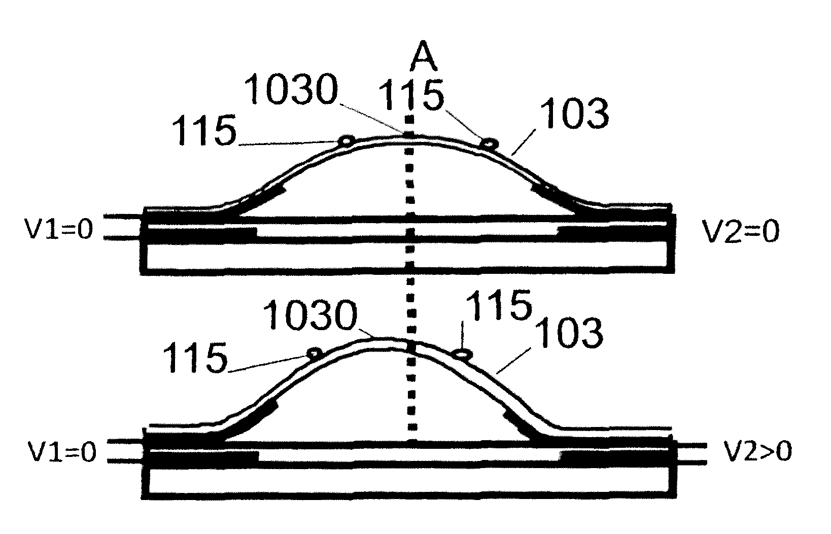
View PDF73 Cites 34 Cited by
  • Summary
  • Abstract
  • Description
  • Claims
  • Application Information

AI Technical Summary

Benefits of technology

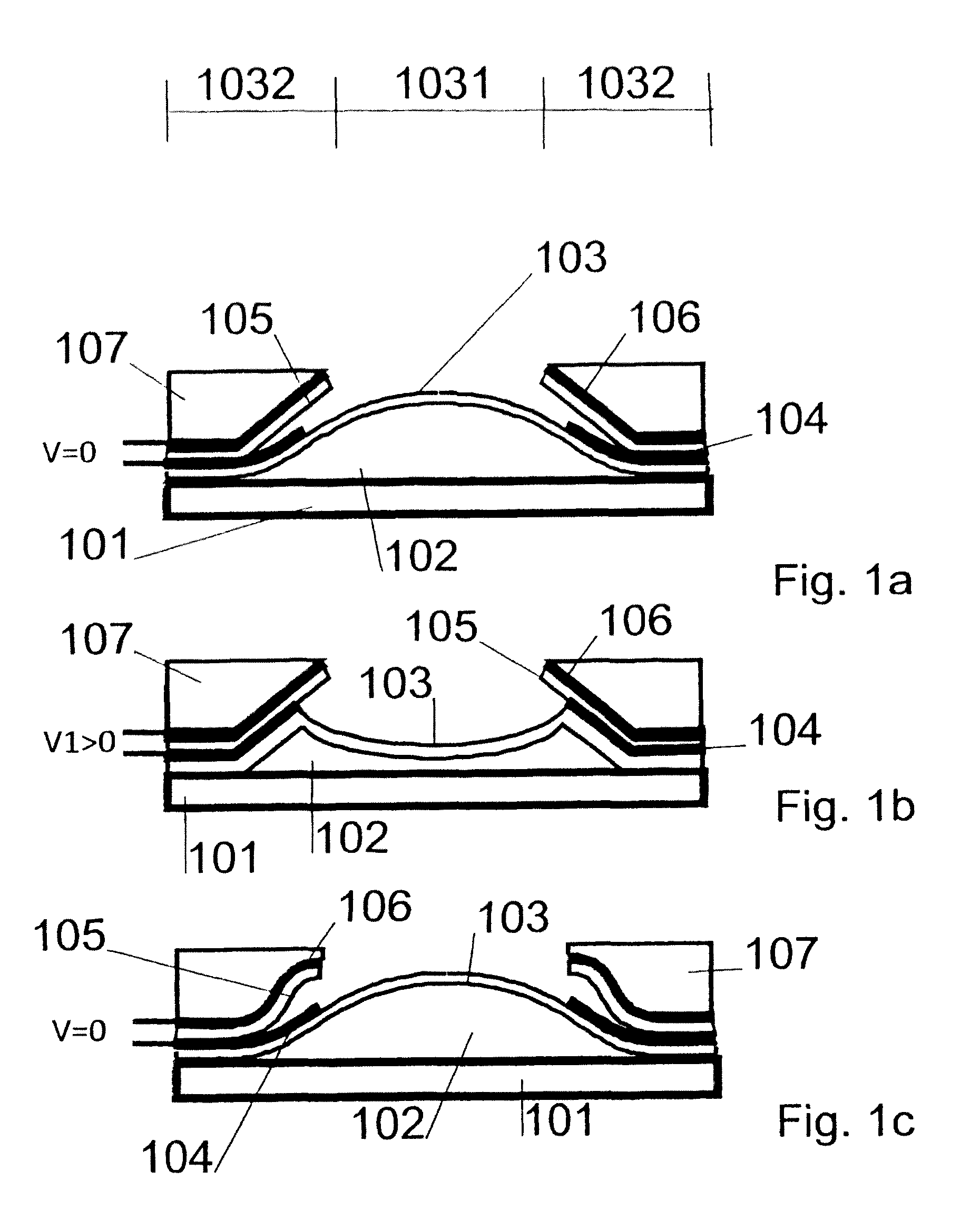
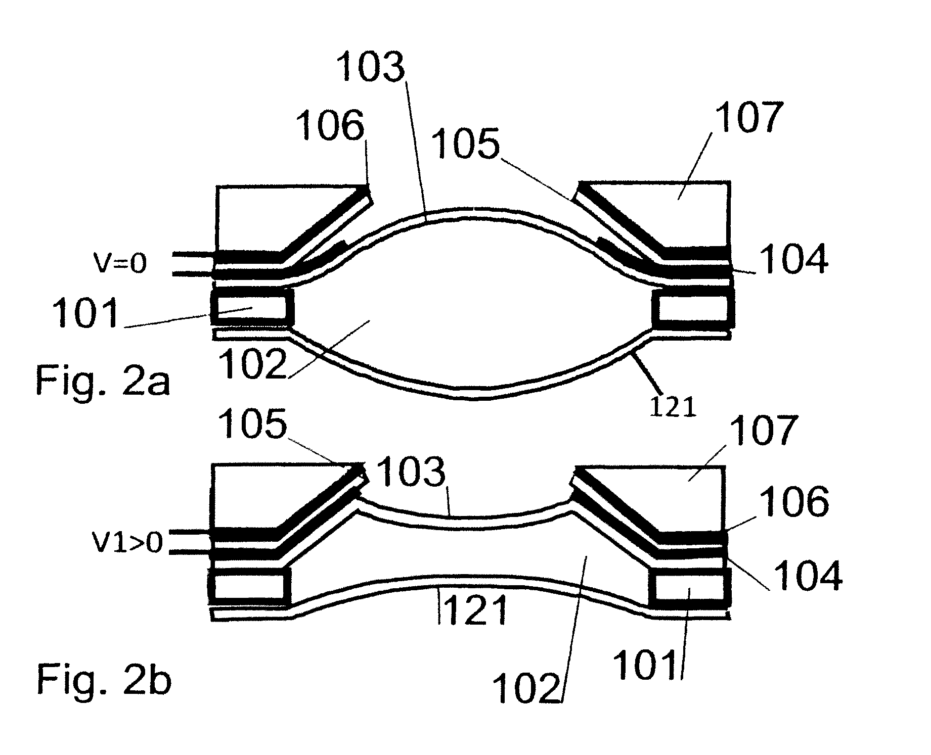
[0006]The problem to be solved by the present invention is therefore to provide an adjustable optical lens which is a compact assembly.
[0011]In a preferred embodiment, a holder for the second electrode is arranged above the membrane. An assembly comprising the holder, the second electrode, and advantageously an insulation layer my form a prefabricated assembly. Such assembly may be applicable to many different membrane / support assemblies, and may form a standard assembly for optical lenses irrespective of specific properties of such lenses. When it comes to manufacturing, the sealing of the fluid normally is a low yield process. If the costly deposition processes for the second electrode and the insulation layer do not need to be done on the support, the overall costs after yield lost can be improved.

Problems solved by technology

In addition, the lens according to the art is limited in its applications since the portion of the membrane that is elevated provides for a peak during elevation which peak persistently is well-centred.

Method used


Image

  • Adjustable optical lens
  • Adjustable optical lens
  • Adjustable optical lens

Examples


Embodiment Construction

[0031]Similar or relating elements in the several figures are provided with the same reference numerals.

[0032]Definitions

[0033]The term “axial” is generally used to designate a direction perpendicular to the surface of the membrane and generally parallel to the direction of the light path. For the reason that the membrane in the present application often takes a convex / concave shape it is assumed that the term axial may also refer to an assumed plain shape of the overall adjustable optical lens, most of the times coinciding with a plain surface of the support, and therefore be defined as a direction perpendicular to such surface. The term “lateral” is used to designate a direction perpendicular to the axial direction, i.e. a direction parallel to the support.

[0034]The terms “interior” and “periphery” both refer to portions of the membrane. While the membrane in a relaxed, non-stressed state typically is a plain element of e.g. triangular, rectangular, circular or polygonal shape, su...


PUM

PropertyMeasurementUnit
thicknessaaaaaaaaaa
thicknessaaaaaaaaaa
resistanceaaaaaaaaaa

Abstract

The disclosure provides an adjustable optical lens comprising a membrane, a support for the membrane, a fluid between the membrane and the support, an actuator for deforming the membrane, and a rigid ring connected to the membrane for moving with the membrane for ensuring that a section of the membrane surrounded by the rigid ring has a defined circumference.

Description

TECHNICAL FIELD[0001]The invention relates to an adjustable optical lens, as well as to methods for operating and fabricating such a device.BACKGROUND ART[0002]An adjustable optical lens is an optical device which may be adjusted for varying the focal length as well as the lateral position of the center of optical axis of the device. Such lenses are also known as varifocal displacement lenses provided they can adjust to multiple different focal points.[0003]WO 2008 / 138010 A1 discloses an adjustable lens comprising a rigid base, a deformable membrane on top of the base, and a fluid in between the base and the membrane. A first electrode is attached to the membrane while a second electrode of an electrostatic actuator is attached to the base.[0004]Such a lens constitutes a relatively thick device.[0005]In addition, the lens according to the art is limited in its applications since the portion of the membrane that is elevated provides for a peak during elevation which peak persistently...

Claims


Application Information

Patent Timeline
Patent Type & Authority Patents(United States)
IPC IPC(8): G02B1/06G02B26/00G02B3/12
CPCG02B3/14G02B26/004Y10T29/49002
Inventor ASCHWANDEN, MANUELGRAETZEL, CHAUNCEYKEM, THOMASGEBBERS, PIT
Owner OPTOTUNE AG
Learn More