
Tampon applicator

a technology of tampons and applicators, which is applied in the field of tampon applicators and tampon applicators, can solve the problems of affecting affecting the effect of insertion, etc., and achieves the effects of enhancing the comfort of users during insertion, reducing the risk of insertion, and improving the effect of flushability and compostability

Inactive Publication Date: 2014-06-24
EVEREADY BATTERY CO INC
View PDF59 Cites 4 Cited by
  • Summary
  • Abstract
  • Description
  • Claims
  • Application Information

AI Technical Summary

Benefits of technology

The present invention is about a tampon applicator made from pulp-based material. The invention has several technical advantages. Firstly, the barrel and plunger of the applicator can be molded using a process comparable to or faster than injection molding, which makes the process more efficient and cost-effective. Secondly, the barrel can have a textured surface, gripping structures, or both, which enhance the user's comfort during insertion. The exterior surface of the barrel can also be molded smoothly, which makes the applicator easier to flush and compost. Lastly, the tampon applicator remains strong and durable. The overall process of molding the tampon applicator using the pulp-based material is efficient and cost-effective.

Problems solved by technology

Although preferred by some women because of a smooth and virtually frictionless exterior surface which enables easy, more comfortable insertion, plastic applicators have, at times, the perception of disposal problems.
The plastic applicators can cause problems when flushed down a toilet, and instead should be disposed of with the dry trash.
This method of disposal raises environmental concerns since most plastics are slow to biodegrade, and most are not compostable.
Also, disposal in dry trash is not as discreet as flushing, which is a concern to many women.
However, paper applicators are commonly thought of as less comfortable to insert, and are more difficult to form into shapes other than uniform cylindrical tubes.
Many paper applicators are coated with a non-compostable coating to strengthen the applicator barrel and / or reduce the coefficient of friction of the barrel, rendering the applicator less environmentally friendly than consumers believe.
Paper applicators also lack the advantage of plastic applicators of being able to be molded into more preferred, ergonomic and easier-to-use forms.

Method used


Image

  • Tampon applicator
  • Tampon applicator
  • Tampon applicator

Examples


Embodiment Construction

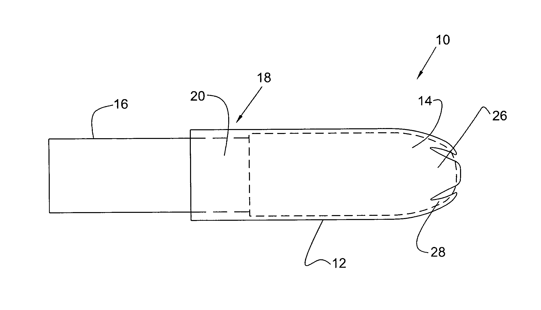
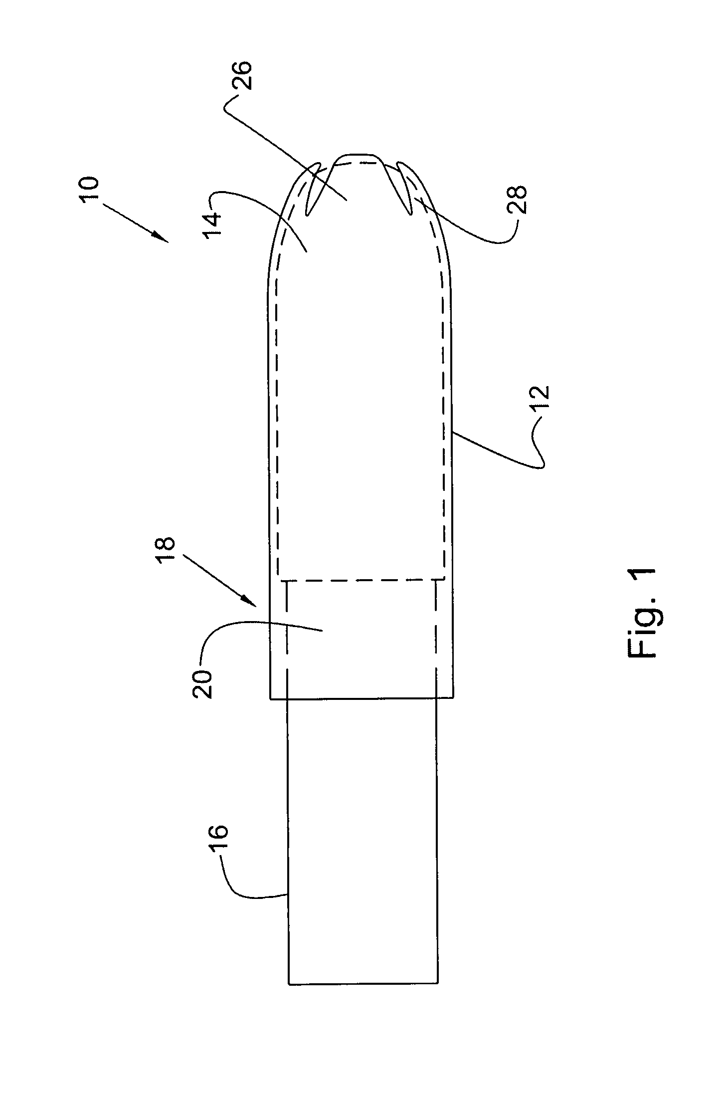
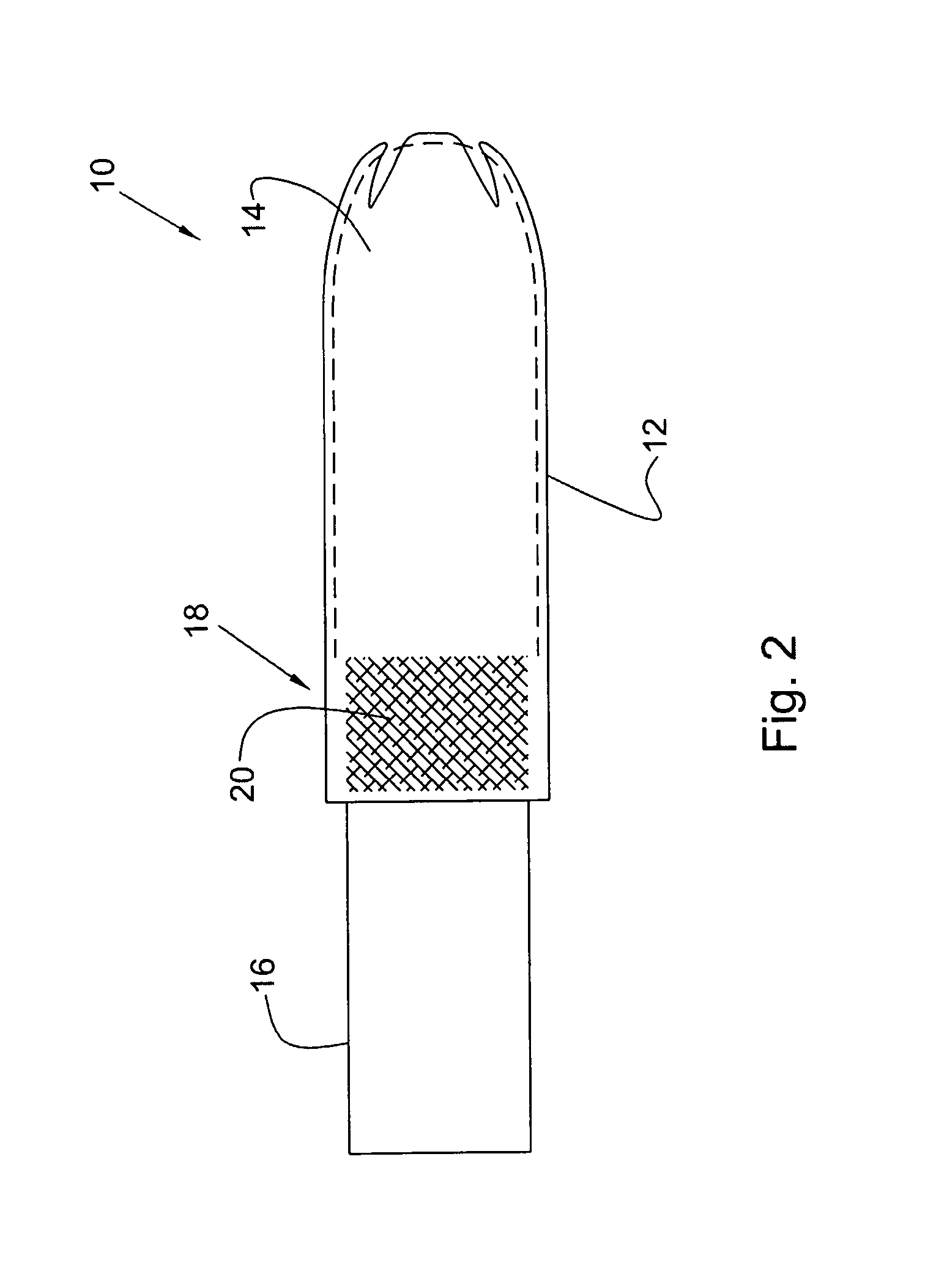
[0023]Referring to the drawings, and in particular FIG. 1, the tampon applicator of the present invention is represented generally by reference numeral 10. Tampon applicator 10 has a barrel 12 that can house a pledget 14 therein and a plunger 16 that can be connected to the barrel to engage, telescopically, the pledget housed in the barrel. Preferably, barrel 12 has a plunger receiving end or portion 18 and a fingergrip area 20 preferably adjacent end 18. According to the present invention, either barrel 12 and / or plunger 16 are made from a pulp-based material. Barrel 12 also has a pledget ejection portion or end 28. Ejection end 28 can be open-ended or have individual petals or connected, such as louvered together, petals. Preferably, end 28 has one or more individual petals 26. More preferably, end 28 has at least two petals 26. Petals 26 enclose pledget 14 upon insertion of applicator 10 into the vagina, resulting in user comfort. By including two or more petals 26, ejection forc...


PUM

PropertyMeasurementUnit
coefficient of frictionaaaaaaaaaa
thermoplasticaaaaaaaaaa
grip areaaaaaaaaaaa

Abstract

A tampon applicator is provided having a barrel and / or a plunger molded from a pulp-based material. The barrel can be molded such that it includes a molded fingergrip area having a textured surface, at least one gripping structure, or any combination thereof. Petals may be molded on the pledget ejection end of the barrel. In addition, the exterior surface of the barrel is molded such that it is textured, smooth, or any combinations thereof. The molded tampon applicator exhibits superior flushability and compostability characteristics, without compromising the strength of the barrel or plunger.

Description

CROSS REFERENCE TO RELATED PATENT APPLICATIONS[0001]This application is a divisional of U.S. patent application Ser. No. 11 / 061,557, filed on Feb. 18, 2005 entitled “Tampon Applicator,” which is a continuation of U.S. patent application Ser. No. 10 / 271,201, filed on Oct. 15, 2002, which claims the benefit of U.S. Provisional Application No. 60 / 330,105, filed on Oct. 17, 2001. The aforementioned applications are herein incorporated by reference in their entirety.BACKGROUND OF THE INVENTION[0002]1. Field of the Invention[0003]The present invention relates to an insertion device, such as a catamenial or tampon applicator. More particularly, the present invention relates to a tampon applicator formed from a molded pulp-based material.[0004]2. Description of Related Art[0005]The majority of tampon applicators on the market are manufactured from plastic, cardboard, or combinations of the two materials. Although preferred by some women because of a smooth and virtually frictionless exterio...

Claims


Application Information

Patent Timeline
Patent Type & Authority Patents(United States)
IPC IPC(8): B22D11/126
CPCY10T29/49885Y10T29/49982Y10T29/49984Y10T29/49888A61F13/2085Y10T29/4998
Inventor JARMON, GEORGEPHAM, VAN
Owner EVEREADY BATTERY CO INC
Learn More