Vibrating gyro device and manufacturing method therefor

a gyro device and vibrating technology, applied in the direction of turn-sensitive devices, acceleration measurement using interia forces, instruments, etc., can solve the problems of bending affecting the accuracy of the vibrating board, and the size of the device is not suitable to reduce, so as to reduce the amount of piezoelectric material used to manufacture the piezoelectric substrate, the effect of reducing the amount of processing required in the etching step to pattern the pi

Inactive Publication Date: 2014-06-24
MURATA MFG CO LTD
View PDF30 Cites 23 Cited by
  • Summary
  • Abstract
  • Description
  • Claims
  • Application Information

AI Technical Summary

Benefits of technology

[0011]A vibrating gyro device according to a preferred embodiment of the present invention preferably includes a piezoelectric substance, a pair of main surface electrodes and a supporting body. The piezoelectric substance preferably includes an inner opening portion and an outer opening portion. An inner side surface of a frame-shaped region in a main surface of the piezoelectric substance is exposed through the inner opening portion. An outer side surface of the frame-shaped region is exposed through the outer opening portion. Preferably, the pair of main surface electrodes are bonded to the front and back main surfaces of the frame-shaped region and are electromechanically coupled with displacement of the frame-shaped region in a direction perpendicular or substantially perpendicular to the main surface of the piezoelectric substance and with displacement of the frame-shaped region in a direction parallel or substantially parallel to the main surface of the piezoelectric substance. The supporting body provides a vibration space for the frame-shaped region and supports the piezoelectric substance. The vibration space prevents other members from interfering with the frame-shaped region and the inner opening portion and the outer opening portion are connected therethrough.
[0026]According to various preferred embodiments of the present invention, a vibrator preferably includes a pair of main surface electrodes arranged in a frame-shaped region of a piezoelectric substance. Therefore, even though the vibrating gyro device has a small size due to the omission of a vibrating board, the frame-shaped region vibrates and deformation due to the Coriolis force can be generated. Furthermore, as a result of providing the inner opening portion and the outer opening portion in the piezoelectric substance, the weight of the piezoelectric substance is reduced such that the restraint of the frame-shaped region around the boundary thereof is reduced and thereby stress acting on the frame-shaped region is reduced. Consequently, strain is reduced and the vibration mode of the frame-shaped region is appropriately maintained. As a result, the detection accuracy of the vibrating gyro device is ensured even though the thickness of the vibrator is reduced. Furthermore, since bending of the piezoelectric substance due to its own weight is prevented, the risk of the piezoelectric substance coming into contact with the supporting body is reduced and the size of the vibration space can be reduced.

Problems solved by technology

216-224, February 2004 and JP Patent No. 3218702), for each vibrator, only a single detection axis can be provided and a plurality of vibrators are required to provide a plurality of detection axes, which is not suitable to reduce the size of the device.
In particular, in a configuration in which electrodes are not only formed on the front and back but also on the side surfaces of a vibrator, since the forming of electrodes and wiring therefor on the side surfaces is difficult when the size of the vibrator is reduced, there are limits on how thin the vibrator can be made.
Furthermore, there is a risk of the vibrating board bending and thereby coming into contact with a supporting body and, therefore, it is necessary to provide a larger vibration space.
Therefore, there are limits to how thin the vibrating board can be made.

Method used


Image

  • Vibrating gyro device and manufacturing method therefor
  • Vibrating gyro device and manufacturing method therefor
  • Vibrating gyro device and manufacturing method therefor

Examples


Embodiment Construction

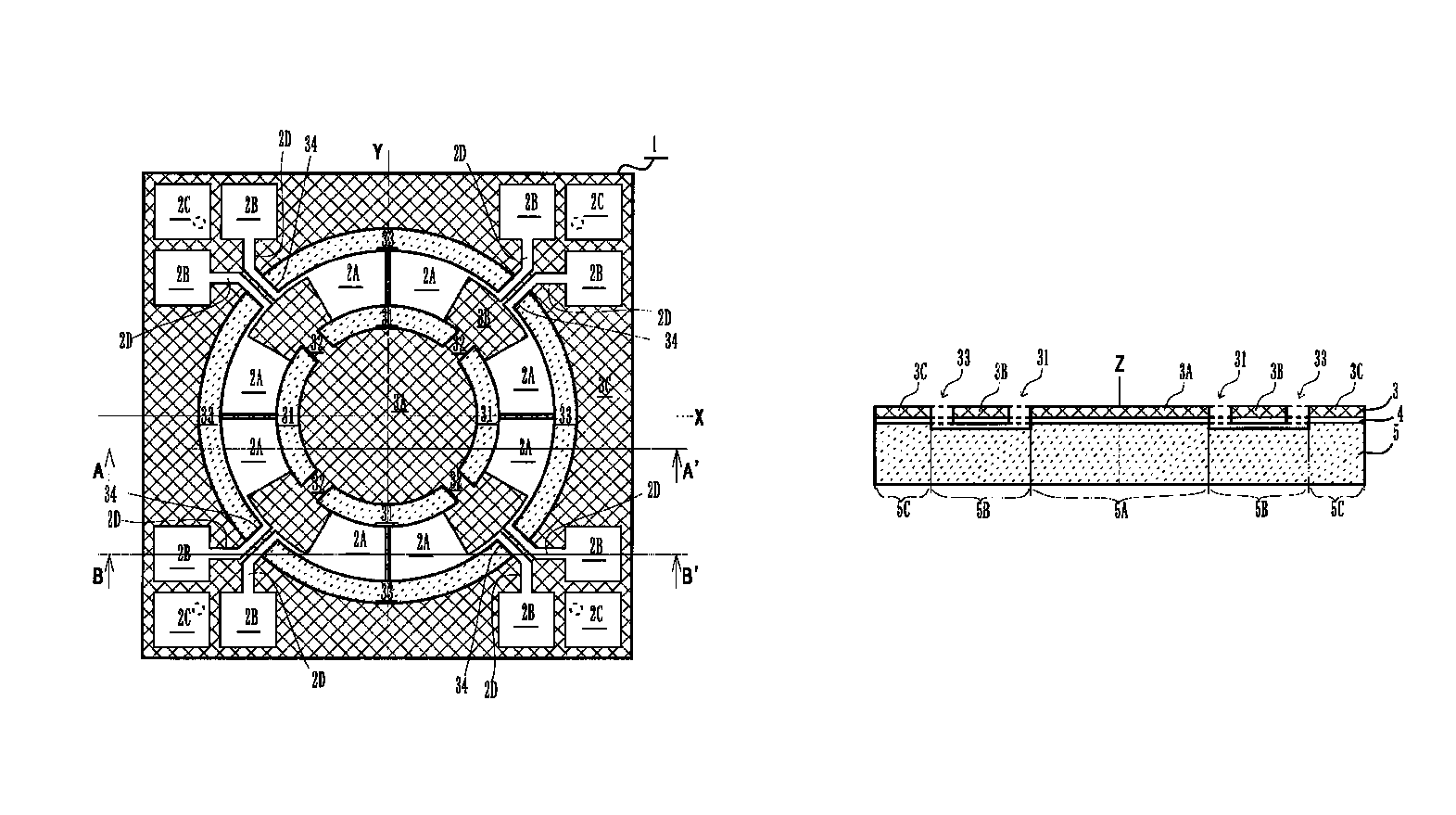
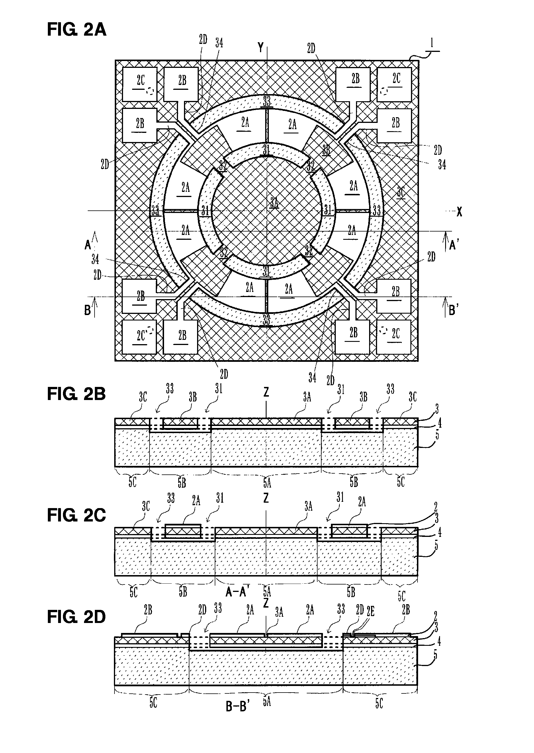
[0034]A vibrating gyro device according to a first preferred embodiment of the present invention will be described. FIGS. 2A to 2D show an example configuration of a vibrating gyro device. FIG. 2A is a top view, FIG. 2B is a central sectional view, FIG. 2C is a sectional view along line A-A′ and FIG. 2D is a sectional view along line B-B′.

[0035]A vibrating gyro device 1 preferably has a shape that is axisymmetrical about an X axis, which defines an axis of symmetry, and that is axisymmetrical about a Y axis, which also defines an axis of symmetry, so as to be capable of detecting rotation about two perpendicular axes (X axis and Y axis). Furthermore, a support substrate 5, a lower main surface electrode 4, a piezoelectric substrate 3, and an upper main surface electrode 2 are preferably stacked on top of one another in this order from the bottom upward along a Z axis, which is perpendicular to the X-Y plane.

[0036]The support substrate 5 and the piezoelectric substrate 3 are preferab...


PUM

PropertyMeasurementUnit
thicknessaaaaaaaaaa
thicknessaaaaaaaaaa
thicknessaaaaaaaaaa

Abstract

A vibrating gyro device includes a piezoelectric substrate, an upper main surface electrode, a lower main surface electrode, and a support substrate. The piezoelectric substrate is provided with inner open holes and outer open holes. Side edge surfaces of a frame-shaped region in the X-Y plane are exposed to the interior of the frame through the inner open holes. Side edge surfaces of the frame-shaped region are exposed to the exterior of the frame through the outer open holes. Drive detection electrodes arranged within the upper main surface electrode are bonded to the upper main surface of the frame-shaped region and together with the lower main surface electrode are electromechanically coupled with deformation of the frame-shaped region in the Z-axis direction and deformation of the frame-shaped region in a direction parallel or substantially parallel to the X-Y plane. The support substrate provides a vibration space for the frame-shaped region and supports the piezoelectric substrate. The vibration space prevents interference between the frame-shaped region and the support substrate and connects the inner open holes and the outer open holes.

Description

BACKGROUND OF THE INVENTION[0001]1. Field of the Invention[0002]The present invention relates to vibrating gyro devices that detect rotation by utilizing deformation of a piezoelectric substance in a direction perpendicular or substantially perpendicular to a main surface of the piezoelectric substance and deformation of the piezoelectric substance in a direction parallel or substantially parallel to a main surface of the piezoelectric substance, and also relates to methods for manufacturing such vibrating gyro devices.[0003]2. Description of the Related Art[0004]A vibrating gyro device that detects rotation includes, for example, a vibrating board to which a piezoelectric ceramic has been affixed or a vibrating board made of a piezoelectric single crystal, such as quartz, lithium niobate, or lithium tantalate, and detects the Coriolis force acting on the vibrator. Such vibrators have a variety of shapes including a tuning fork shape, a square-cross-section tuning bar shape, an equi...

Claims


Application Information

Patent Timeline
Patent Type & Authority Patents(United States)
IPC IPC(8): H01L41/22G01C19/56G01C19/5755H01L41/312H01L41/332
CPCH01L41/1873Y10T29/42H01L41/047G01C19/5755H01L41/081H01L41/332
Inventor YONEDA, TOSHIMAROKAMBAYASHI, TSUGUJI
Owner MURATA MFG CO LTD
Why Eureka
Try Eureka