Grip mounted safety shield
a safety shield and mounting technology, applied in the field of grip shields, can solve the problems of increasing the speed of the jaw face, and the user's severe pinching injury, and achieve the effect of reducing the risk of pinching accident and not affecting productivity
- Summary
- Abstract
- Description
- Claims
- Application Information
AI Technical Summary
Benefits of technology
Problems solved by technology
Method used
Image
Examples
first embodiment
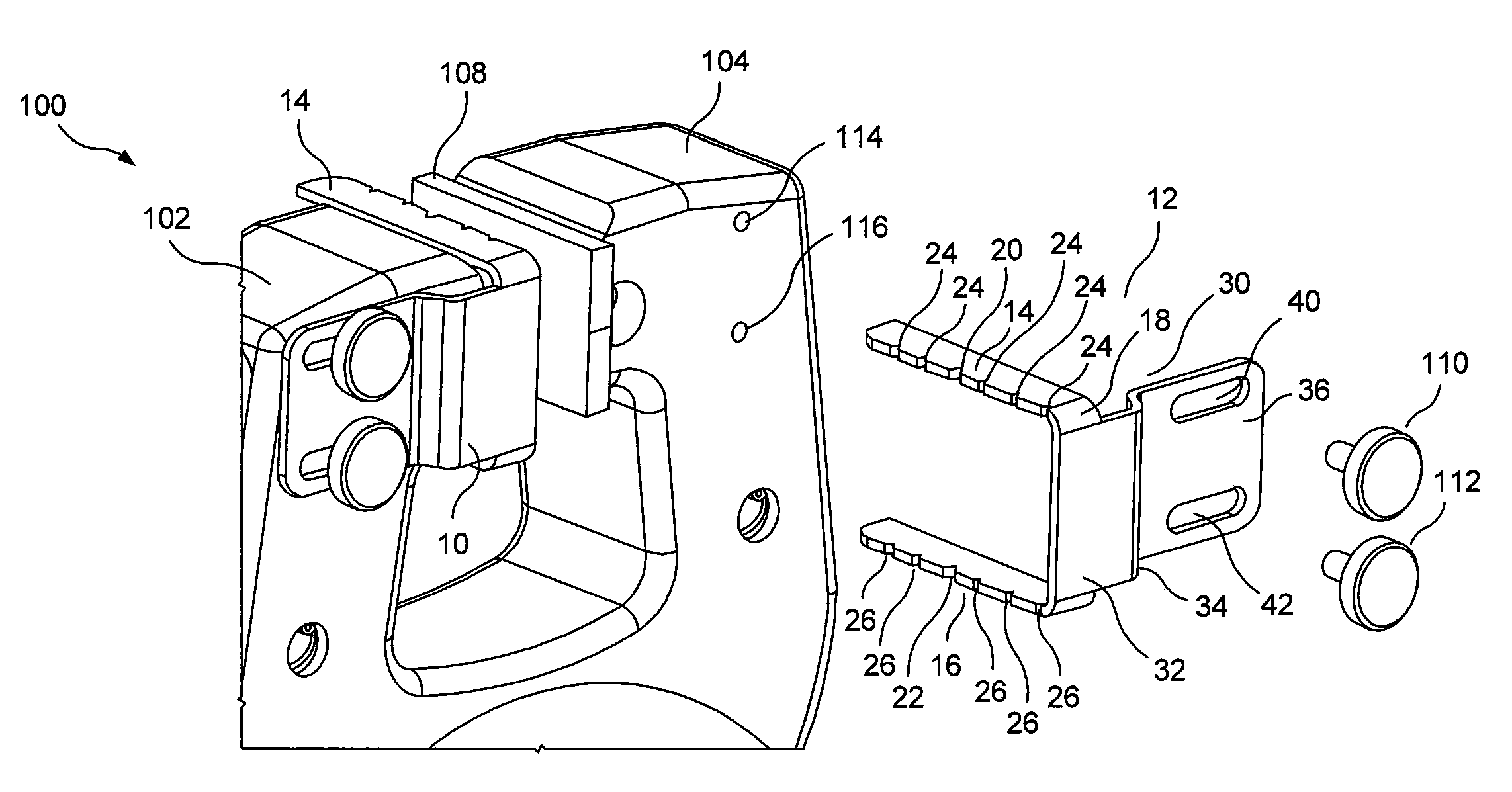
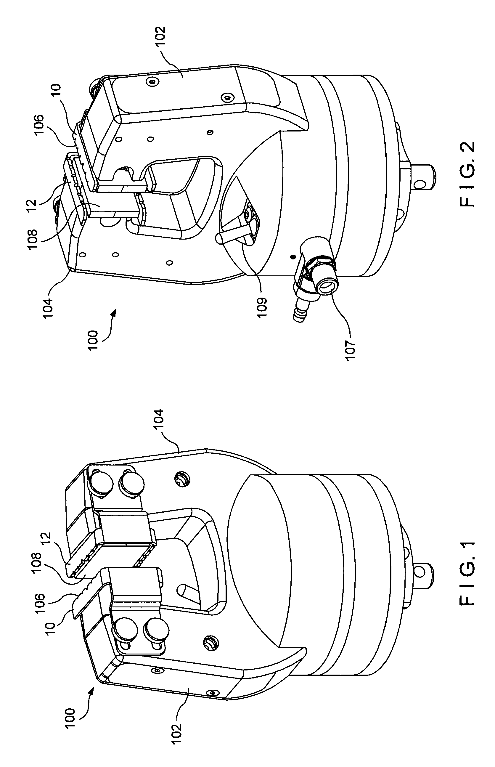
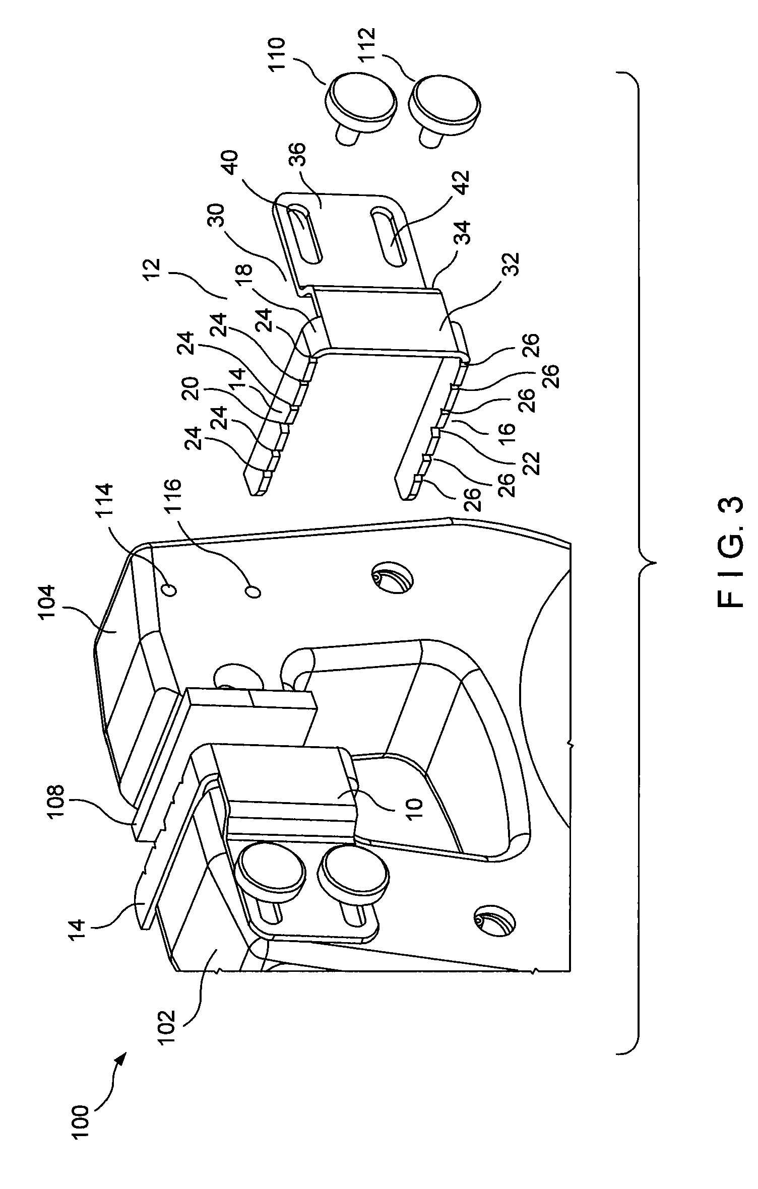
[0013]Referring now to the drawings in detail wherein like numerals indicate like elements throughout the several views, one sees that FIGS. 1-3 illustrate a grip 100 such as is used in materials testing, with first and second safety shields 10, 12. Grip 100 includes first and second jaws 102, 104 with opposed first and second jaw faces 106, 108 which reciprocate toward and away from each other. As is known in the prior art, first and second jaw faces 106, 108 grip a tensile material testing sample or specimen (not shown) and, in combination with a similar opposed grip, typically pull or compress the sample in a direction parallel to the first and second jaw faces 106, 108. FIG. 2 illustrates the pneumatic or hydraulic port 107 and the control switch 109 of the grip 100.
[0014]First and second safety shields 10, 12 are mounted on respective first and second jaws 102, 104 with a view to preventing the user's fingers from entering between first and second jaw faces 106, 108 when the te...
second embodiment
[0017]A second embodiment is illustrated in FIGS. 4 and 5. First and second safety shields 50, 52 are formed from a length of wire which is shaped to cover two or three sides of the first and second jaw faces 106, 108. Each safety shield 50, 52 is typically formed from a single continuous length of metal wire. Top and bottom horizontal bent-back portions (or loops) 54, 56 form respective upper and lower shields. Top and bottom horizontal bent-back portions 54, 56 include two sections of wire oriented substantially parallel to each other and joined by a sharp bend. Top and bottom horizontal bent-back portions 54, 56 are joined to each other by central vertical bent-back portion (or loop) 58 which is configured and arranged to receive screw 118 to mount the first and second safety shields 50, 52 on respective first and second mounting surfaces 120, 122 on the respective first and second jaws 102, 104. The first and second mounting surfaces 120, 122 include a threaded aperture (not sho...
PUM
| Property | Measurement | Unit |
|---|---|---|
| length | aaaaa | aaaaa |
| tensile testing | aaaaa | aaaaa |
| material properties | aaaaa | aaaaa |
Abstract
Description
Claims
Application Information
 - R&D
- Intellectual Property
- Life Sciences
- Materials
- Tech Scout
- Unparalleled Data Quality
- Higher Quality Content
- 60% Fewer Hallucinations
Browse by: Latest US Patents, China's latest patents, Technical Efficacy Thesaurus, Application Domain, Technology Topic, Popular Technical Reports.
© 2025 PatSnap. All rights reserved.Legal|Privacy policy|Modern Slavery Act Transparency Statement|Sitemap|About US| Contact US: help@patsnap.com


