Piston with a duct under a gasket

a technology of ducts and gaskets, applied in the field of pistons, can solve the problems of reducing the fluid flow rate through the duct, and achieve the effects of facilitating maintenance of the duct, minimizing the tendency of the duct to clog, and low cos

Active Publication Date: 2014-06-24
SN DETUDE & DE CONSTR DE MOTEURS DAVIATION S N E C M A
View PDF11 Cites 5 Cited by
  • Summary
  • Abstract
  • Description
  • Claims
  • Application Information

AI Technical Summary

Benefits of technology

[0007]The present invention seeks to propose a piston that makes it possible, at low cost, to establish a flow of fluid between the two chambers separated by the piston, while minimizing any tendency for the duct to clog, and while also facilitating maintenance of the duct.
[0009]By means of these provisions, any risks of clogging the duct passing through the piston are minimized, since there is no longer any need for the duct to present a cross-section smaller than some given size. It is the obstacle in the intermediate segment that impedes the flow of fluid therealong, and consequently that reduces the fluid flow rate through the duct. Such a duct is easily made, since, by way of example, the intermediate segment may be made by machining the groove, with the intermediate segment subsequently being closed over its entire side wall by the gasket that is placed in the groove. Similarly, access to the intermediate segment for cleaning it is made easy, since it suffices to remove the gasket from the groove in order to gain access to the intermediate segment.

Problems solved by technology

It is the obstacle in the intermediate segment that impedes the flow of fluid therealong, and consequently that reduces the fluid flow rate through the duct.

Method used


Image

  • Piston with a duct under a gasket
  • Piston with a duct under a gasket
  • Piston with a duct under a gasket

Examples


Embodiment Construction

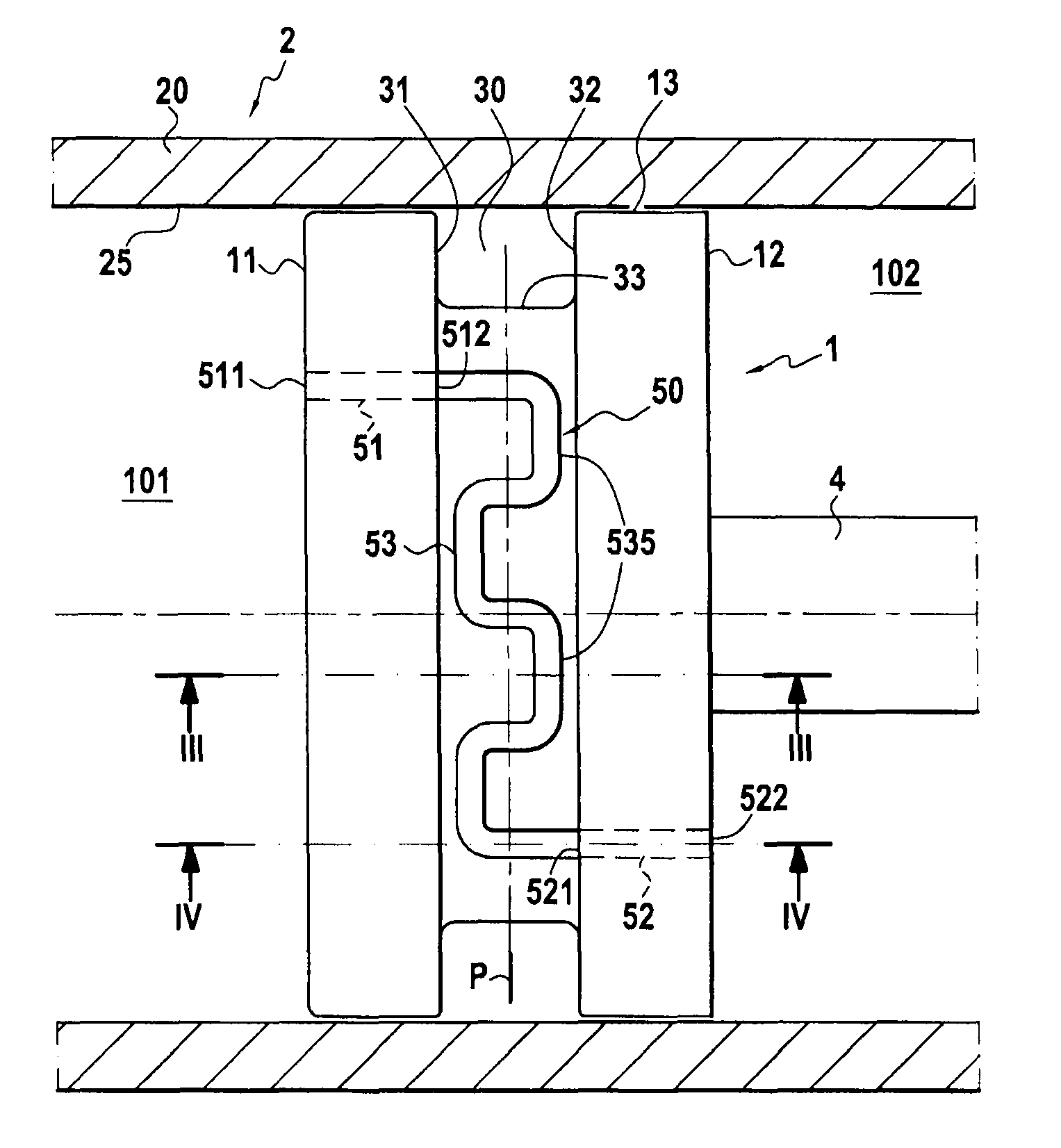
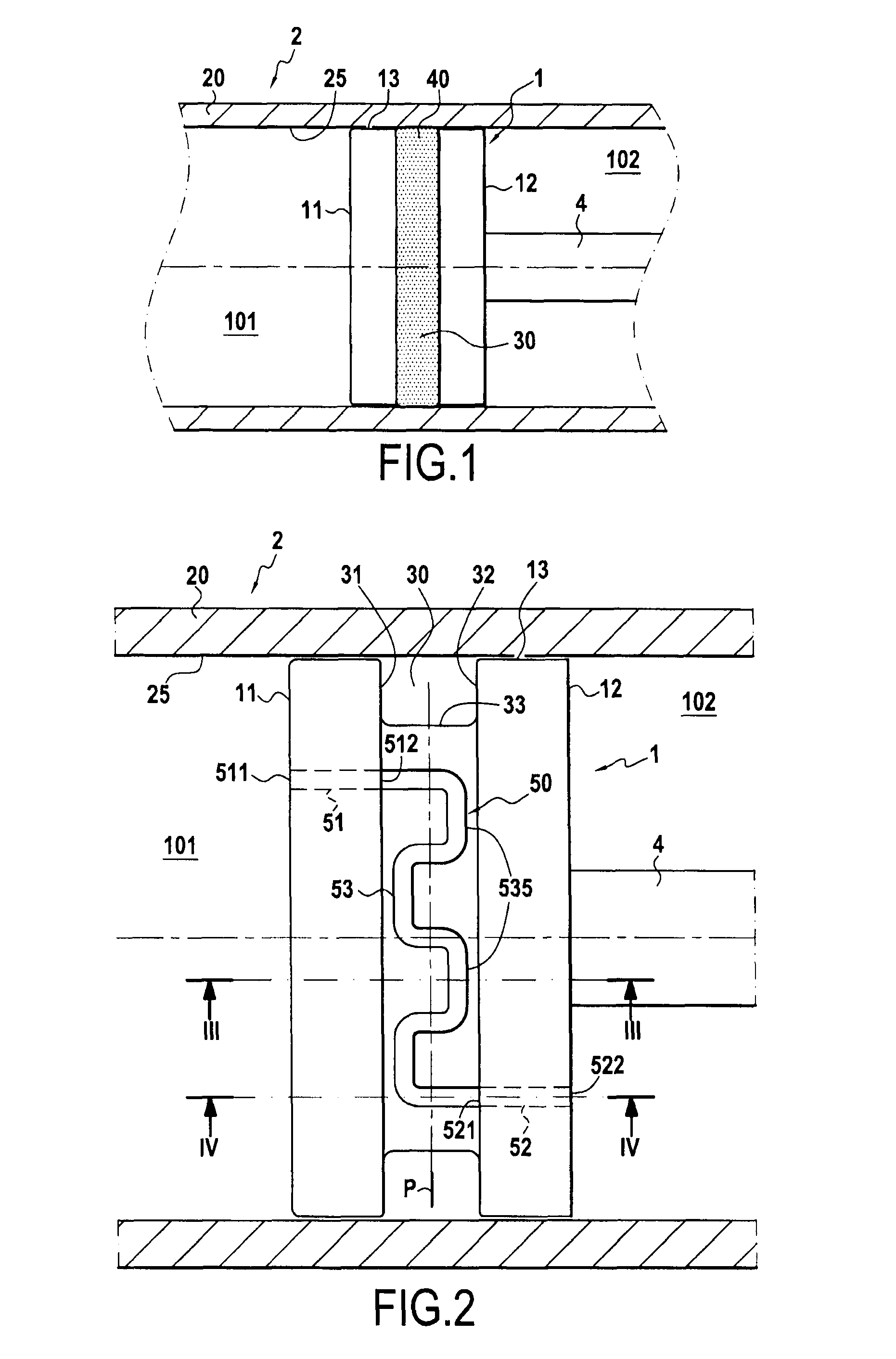
[0020]FIG. 1 is a diagrammatic section view of a piston 1 of the invention situated in an actuator 2 for actuating a device. In the description below, the piston 1 is considered as being situated in an actuator 2, however the piston of the invention is not necessarily situated in an actuator.

[0021]The piston 1 separates a first chamber 101 in leaktight manner from a second chamber 102. The piston 1 is mounted on a rod 4 having a longitudinal axis A, and it therefore slides along the axis A. The piston 1 presents a first face 11 beside the first chamber 101, and a second face 12 opposite from the first face 11 and beside the second chamber 102. By way of example, the first face 11 and the second face 12 are substantially parallel and present an outline in the form of a circle. The first face 11 and the second face 12 are united by a third face 13 constituting an annular face that extends along the longitudinal axis A and that constitutes the radially outer face of the piston 1. When ...


PUM


Abstract

The invention relates to a piston having a first face, a second face opposite to the first face, a third face connecting said first and second faces together and presenting a groove, and a sealing gasket housed in said groove. The piston includes a duct constituted by a first segment situated inside the piston and connecting said first face to said groove, by a second segment situated inside the piston and connecting said second face to said groove, and by an intermediate segment connecting together said first and second segments and crossing said groove, the walls of said intermediate segment being formed by the walls of said groove and by said sealing gasket in such a manner that said intermediate segment forms a leaktight tube that opens out solely via the first segment and via the second segment, said intermediate segment presenting at least one obstacle suitable for impeding the flow of fluid that flows along said intermediate segment.

Description

FIELD OF THE INVENTION[0001]The present invention relates to a piston having a first face, a second face opposite to the first face, a third face connecting said first and second faces together and presenting a groove, and a sealing gasket housed in said groove.BACKGROUND OF THE INVENTION[0002]A piston is an element that separates two chambers (a first chamber and a second chamber), each containing a fluid. For example, in an actuator, the actuator piston is suitable for moving in an actuator cylinder under drive from the fluid contained in the first chamber so as to exert an action on the fluid contained in the second actuator chamber, the fluid in turn exerting action on a piece of equipment that it is desired to actuate.[0003]In order to be effective, the piston must form a leaktight interface between the two chambers, even when the piston is moving in its cylinder.[0004]Nevertheless, in certain situations, it is desirable to maintain fluid flow between the first and second chamb...

Claims


Application Information

Patent Timeline
Patent Type & Authority Patents(United States)
IPC IPC(8): F16J1/09
CPCF01D17/26F05D2260/6022F15B15/1452F15B21/042F16J1/008F16J1/09F15B15/1485F15B21/0423
Inventor BRETTES, FREDERICLAVIE, ALAIN FRANCOIS JEAN
Owner SN DETUDE & DE CONSTR DE MOTEURS DAVIATION S N E C M A
Why Eureka
Try Eureka