Quick-connect mounting apparatus for modular pump system or generator system

a generator system and modular technology, applied in the direction of positive displacement liquid engines, piston pumps, liquid fuel engines, etc., can solve the problems of time-consuming process, time-consuming task, and the filling process would have to come to a halt, and achieve the effect of quick and easy connection, quick and easy coupling, and quick and easy connection to or disconnection

Active Publication Date: 2014-06-24
RAMNARAIN DAVID R +3
View PDF11 Cites 104 Cited by
  • Summary
  • Abstract
  • Description
  • Claims
  • Application Information

AI Technical Summary

Benefits of technology

[0013]The various embodiments of the present invention allow a first mechanism, such as a motor, to be quickly and easily coupled to and decoupled from a second mechanism such as a pump or generator. Further, embodiments of the present invention allow a rotatable member (e.g., a shaft) of a first mechanism to be quickly and easily connected to or disconnected from a rotatable member (e.g., a shaft) of a second mechanism. When the rotatable member of a motor is connected to the rotatable member of a pump or generator, rotation of the motor's rotatable member can impart rotational motion to the rotatable member of the pump or generator. In this fashion the motor powers the pump or generator.
[0014]Embodiments of the present invention can be used with a pump / motor system and allow the user to quickly remove an old pump and install a new pump. Such embodiments allow a user to quickly and easily unlock and separate a motor from a pump. Such embodiments also allow a user to replace the pump by placing a new pump onto a loading area and pushing the pump into place along a track or as constrained by a linkage so as to maintain accurate alignment of the respective shafts. As the user does this, the rail or linkage guides the pump accurately into the desired position where it is joined to the motor and can be locked in place.
[0015]Embodiments of the present invention allow for a “dirty” set of pumps to be removed, and a “clean” set of pumps replaced relatively quickly. The dirty set of pumps can then be cleaned for later reuse at the company's convenience, at a separate cleaning station without undue interruption in the operation of a production line.
[0016]Embodiments of the present invention provide a pump / motor system allowing the pump to be quickly removed from the entire system. Since minimal adjustment is needed for aligning the rotatable members (e.g., the shafts), the pump can be quickly reattached.
[0017]Embodiments of the present invention provide a tapered press-fit coupling. The tapered press-fit coupling is split into two pieces, which allows the remaining half of the coupling to be attached to the pump and half and of the coupling to be attached to the motor. When the two pieces are pressed together they provide alignment and frictional connection which allows the motor to drive the pump. Such embodiments provide a simple locking mechanism to ensure the two pieces of the press-fit coupling to stay connected while the pump and motor are being used. More specifically, the various embodiments of the present invention provide, among other things, (a) a base; (b) a bracket secured to the base and coupled to a first mechanism (e.g., a motor) to support the first mechanism in a fixed position relative to the base, the first mechanism having a first rotatable member (e.g., a shaft); (c) a first engagement member (e.g., a track or arm of a linkage) on the base; and (d) an assembly comprising a second engagement member (e.g., a bearing or another arm of a linkage) and a second mechanism (e.g., a pump or generator) having a second rotatable member. The second engagement member is operatively coupled to the first engagement member to guide the assembly as it is moved between a first position in which the second rotatable member is not attached to the first rotatable member and second position in which the second rotatable member and the first rotatable member are joined together. The various embodiments of the present invention also provide a lock having a locked position temporarily securing the assembly in the second position and an unlocked position permitting movement of the assembly between the first position and the second position.
[0018]By way of example, the lock may include one or more locking means for locking the second mechanism in the second position. The locking means may, for example, include at least one plate secured to the base. Each plate has an elongate slot surrounded by an engagement surface. Such a locking means may also include at least one locking bolt having a shank which extends through the slot in the plate and a head. The head has an unlocked position which allows the second mechanism to move and a locked position in which the head engages the engagement surface to restrict movement of the second mechanism. When such embodiments of the present invention are employed, the second mechanism (e.g., a pump or generator) can easily be removed by loosening the locking bolt(s), moving the assembly including the second mechanism back toward the first position, and then detaching the assembly from the first engagement member. A pump or generator can be reconnected to the motor by reattaching the assembly including the pump or generator to the first engagement member, moving the assembly into the second position and tightening the locking bolt(s).

Problems solved by technology

To date this has been a time-consuming task, sometimes requiring the participation of multiple people skilled in varying trades, including plumbing, electrical, and mechanical repair.
This means that if the machine were to be sanitized, the filling process would have to come to a halt, while employees clean the pump.
This is often a time consuming process.
In the past, these steps have required substantial time, effort and training given the way pumps and motors have been traditionally attached to each other and to the equipment with which they are used.
The old methods used by “contract packaging companies” and others decrease their bottle-per-minute output and thus the profitability of such companies.

Method used


Image

  • Quick-connect mounting apparatus for modular pump system or generator system
  • Quick-connect mounting apparatus for modular pump system or generator system
  • Quick-connect mounting apparatus for modular pump system or generator system

Examples


Embodiment Construction

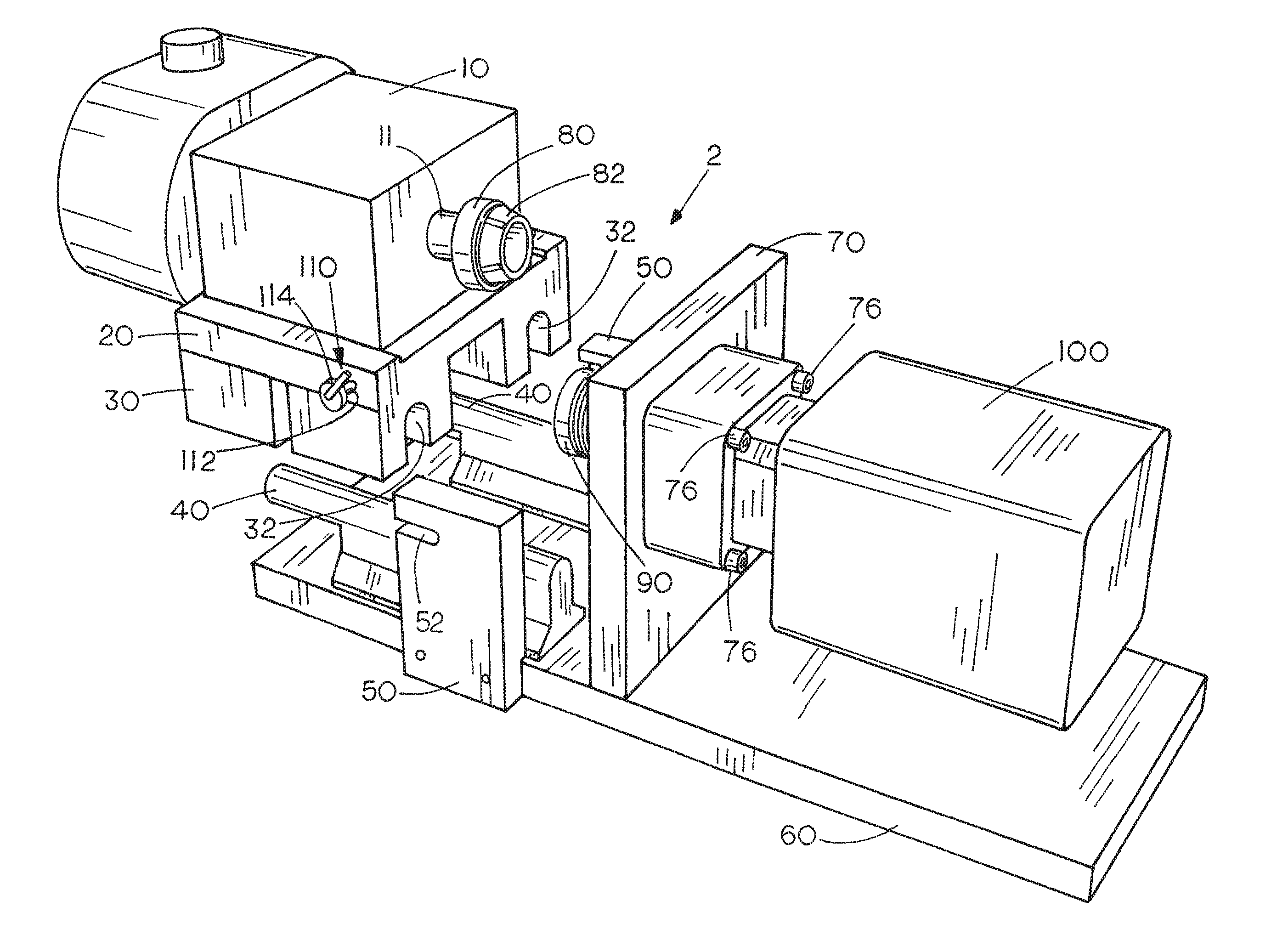
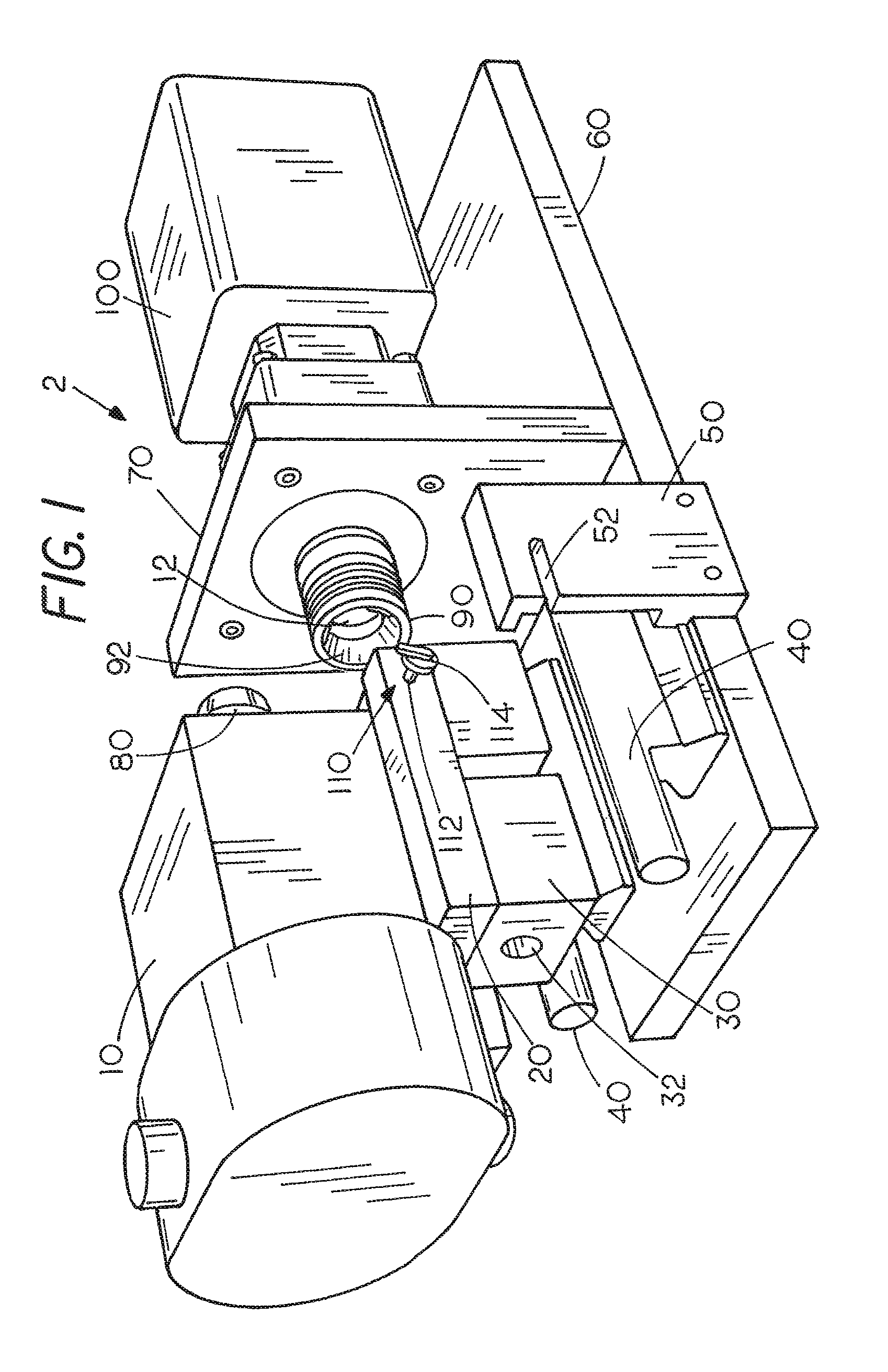
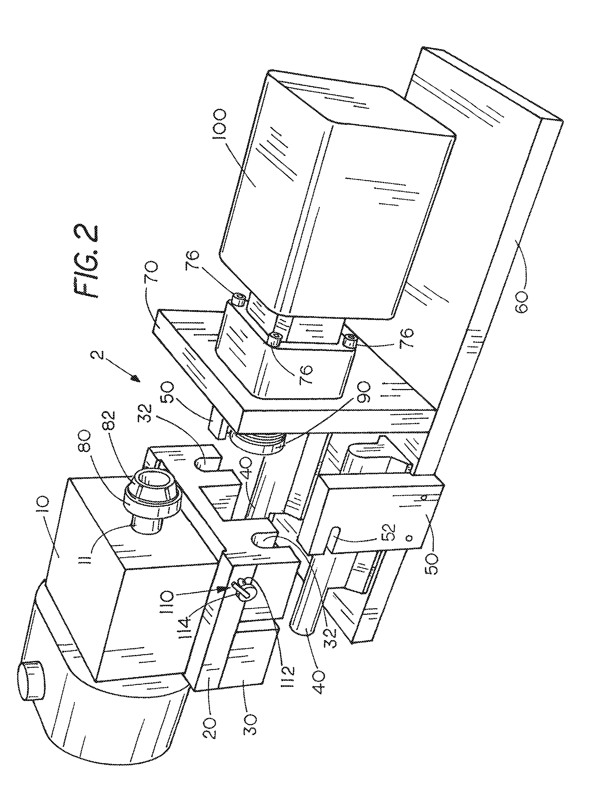
[0036]The following discussion is presented to enable a person skilled in the art to make and use the present teachings. Various modifications to the illustrated embodiments will be readily apparent to those skilled in the art, and the generic principles herein may be applied to other embodiments and applications without departing from the present teachings. Thus, the present teachings are not intended to be limited to embodiments shown, but are to be accorded the widest scope consistent with the principles and features disclosed herein. The following detailed description is to be read with reference to the figures, in which like elements in different figures have like reference numerals. The figures, which are not necessarily to scale, depict selected embodiments and are not intended to limit the scope of the present teachings. Skilled artisans will recognize the examples provided herein have many useful alternatives and fall within the scope of the present teachings.

[0037]Embodime...


PUM


Abstract

A quick-connect mounting apparatus used to join a drive mechanism to a driven mechanism permits rotatable members of the drive mechanism and driven mechanism to be aligned and joined together for proper operation.

Description

CROSS-REFERENCED TO RELATED APPLICATIONS[0001]This application claims priority under 35 U.S.C. §119(e)(1) to U.S. Provisional Application Ser. No. 61 / 286,641, filed Dec. 15, 2009, herein incorporated by reference.STATEMENT REGARDING FEDERALLY SPONSORED RESEARCH OR DEVELOPMENT[0002]Not applicable.BACKGROUND OF THE INVENTION[0003]I. Field of the Invention[0004]The present invention generally relates to systems for quickly connecting and disconnecting a drive member of a first device and a driven member of a second device. Exemplary embodiments of the present invention relate to quick-connect systems for coupling and decoupling the drive member of a motor and a driven member of a pump or generator.[0005]II. Related Art[0006]A pump is a device used to move fluids, such as liquids, slurries, or gases. A pump displaces a volume by physical or mechanical action. For a pump to displace a volume of fluid, power must be supplied to the pump. While power is supplied to some pumps manually, mot...

Claims


Application Information

Patent Timeline
Patent Type & Authority Patents(United States)
IPC IPC(8): F16D1/00
CPCF16D1/10F04B17/03F04B39/14F04B53/22F16D1/033Y10T403/59Y10T403/598
Inventor RAMNARAIN, DAVID R.RAMNARAIN, BRIAN D.RAMNARAIN, PAMELARAMNARAIN, CHRISTOPHER D.
Owner RAMNARAIN DAVID R
Why Eureka
Try Eureka