
Decanted bio-balanced reactor and method

a bio-balanced reactor and decanting technology, applied in biological water/sewage treatment, filtration separation, separation processes, etc., can solve the problems of not treating all the nitrogen contained within the wastewater entering the lagoon, the nitrification rate within the lagoon is so low, and the wastewater biological oxygen demand is reduced, so as to promote the shaking or flexing of the bio media and reduce the effect of biological oxygen demand of the wastewater

Active Publication Date: 2014-06-24
ENVIRONMENTAL DYNAMICS INC
View PDF9 Cites 8 Cited by
  • Summary
  • Abstract
  • Description
  • Claims
  • Application Information

AI Technical Summary

Benefits of technology

The patent describes a wastewater treatment system using a reactor with two bio media zones. The first bio medium is located at the inlet of the reactor and acts as a barrier to prevent short-circuiting of wastewater. It allows the wastewater to flow through it and performs several functions including uniform flow distribution, control of flow distribution, and enhancement of bio flocculation. The aeration system includes submerged diffusers that can dislodge excessive biomass and prevent clogging. The system has a continuous operation phase, a settling phase, a decanting phase, and a secondary treatment phase. The treated wastewater is then discharged from the reactor. The technical effects of this patent include improved wastewater treatment with reduced biological oxygen demand and nitrogenous components conversion, as well as efficient solids separation and retention.

Problems solved by technology

However, some wastewater treatment systems utilizing lagoons are not without disadvantages.
However, in many geographical locations, including the northern half of the United States, as the ambient temperature drops during the fall and winter months, the nitrification rate within the lagoons drops to such a low rate that not all of the nitrogen contained within the wastewater entering the lagoons is treated.

Method used


Image

  • Decanted bio-balanced reactor and method
  • Decanted bio-balanced reactor and method
  • Decanted bio-balanced reactor and method

Examples


Embodiment Construction

[0022]The present invention relates generally to the field of treatment of wastewater, and more particularly to an improved system and method for treating wastewater containing contaminants The system and method can be employed to reduce the solids content, biological oxygen demand (BOD) and nitrogen content of wastewater. It may be implemented in new lagoons, concrete structures or other systems or may be implemented to upgrade existing concrete structures or earthen basin and lagoon type structures in order to bring those systems in conformance with regulations imposed by governmental bodies.

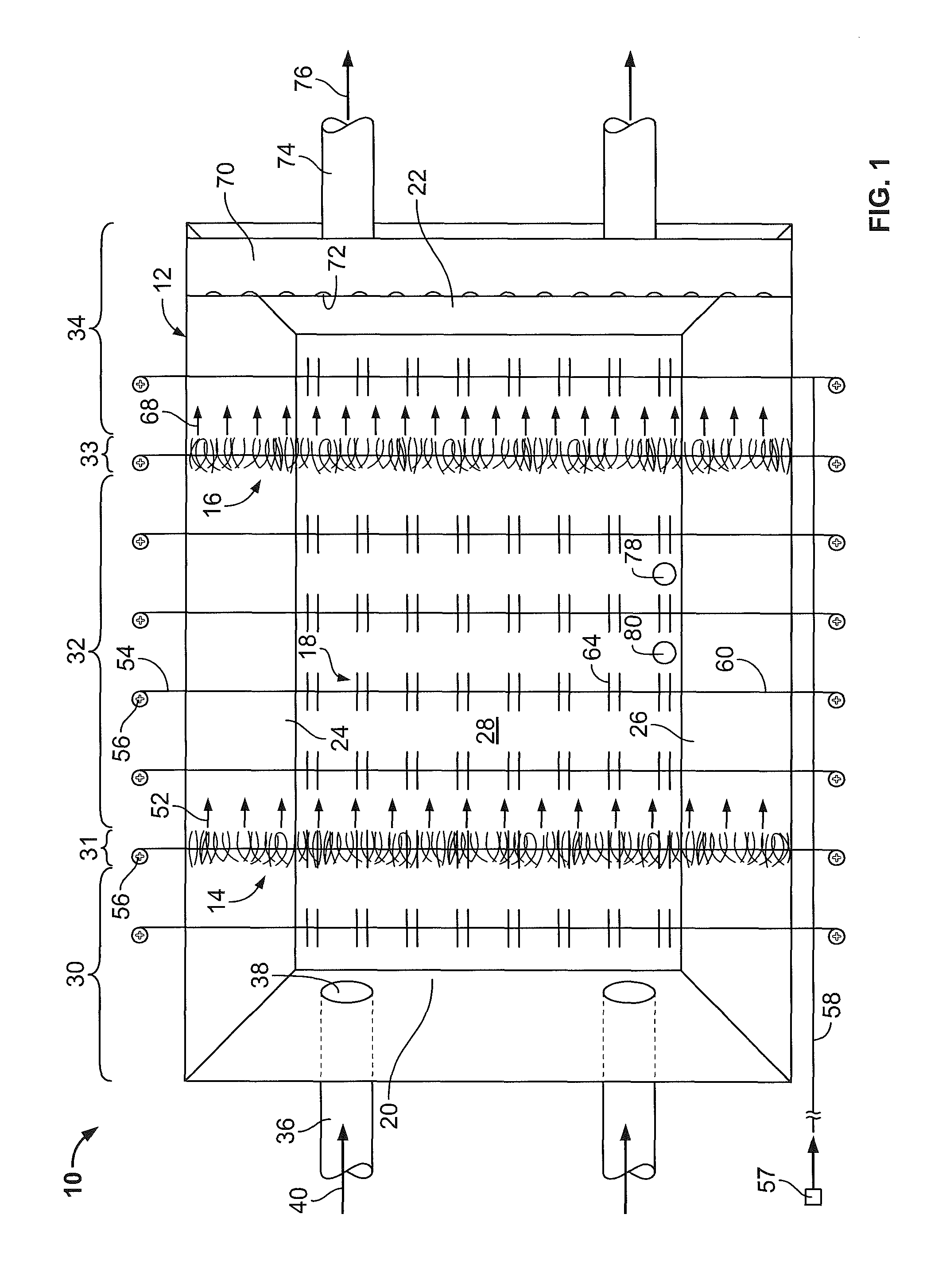
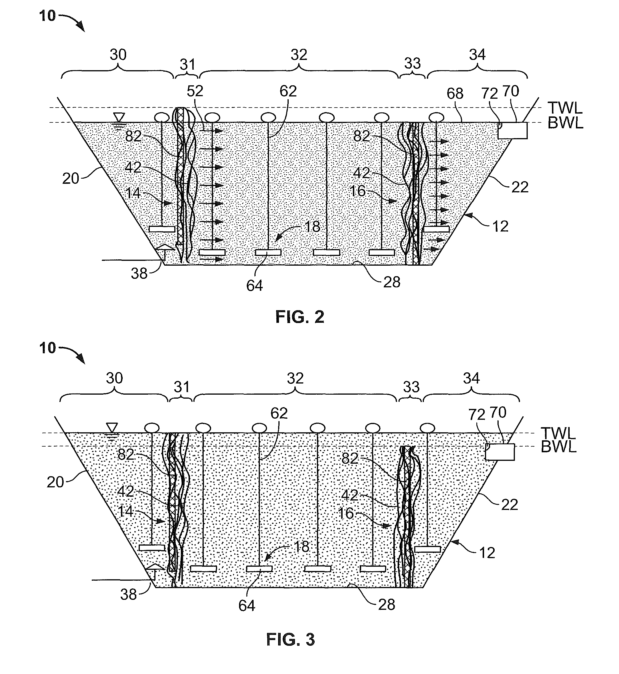
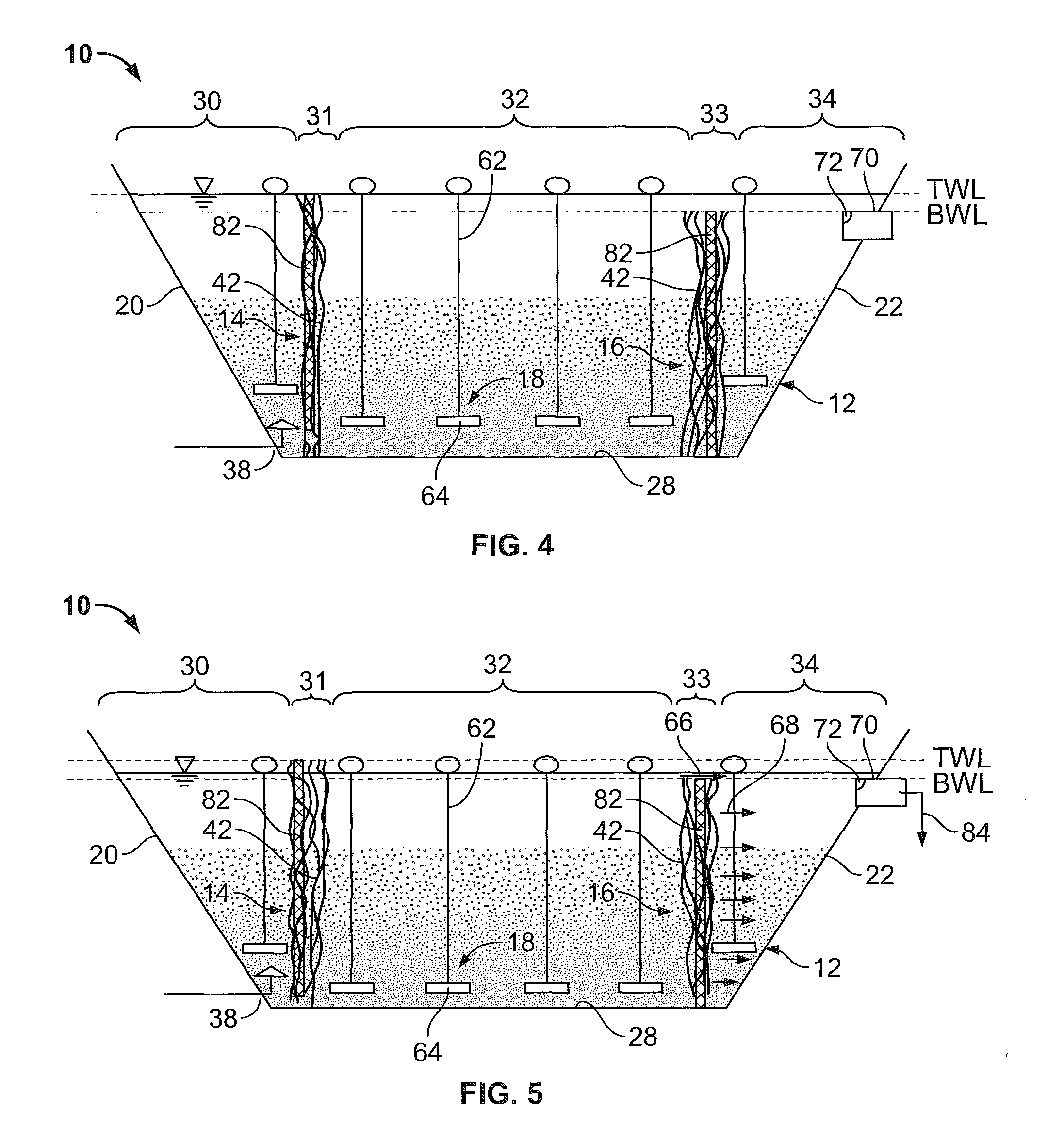
[0023]Referring now to the drawings and initially to FIG. 1, numeral 10 generally designates a wastewater treatment system that includes, among other things, a reactor 12 for containing and treating a liquid such as wastewater, first and second bio media 14 and 16 and an aeration system 18. As will be discussed in greater detail below, the first and second bio media 14 and 16 are adapted and p...


PUM

PropertyMeasurementUnit
timeaaaaaaaaaa
timeaaaaaaaaaa
heightaaaaaaaaaa

Abstract

A wastewater treatment system is provided having a reactor, first and second bio media and an aeration system. The first bio medium is located proximate an inlet end of the reactor and extends vertically between a top water level and the reactor's floor. The second bio medium is located proximate an outlet end of the reactor and extends vertically between a bottom water level and the reactor's floor. The media are adapted for retaining solids within the reactor as clarified water is withdrawn after treatment. The first bio media is further adapted to act as a baffle thereby causing wastewater to flow generally uniformly into a primary reactor zone. The aeration system includes a plurality of diffusers, some of which may be located adjacent or underneath the bio media and are adapted for promoting the shaking the bio media when activated in order dislodge excessive biomass therefrom.

Description

CROSS-REFERENCE TO RELATED APPLICATIONS[0001]None.BACKGROUND OF THE INVENTION[0002]Water and wastewater are commonly treated using a variety of techniques. Many conventional municipal and industrial wastewater treatment plants utilize lagoon technologies in treating wastewater. In many cases, these lagoon technologies are advantageous over alternative options because they require only minimal operator attention, they can be operated by a lower class operator and they require only a relatively small amount of mechanical equipment. Additionally, lagoon technologies are typically capable of minimizing sludge handling procedures.[0003]However, some wastewater treatment systems utilizing lagoons are not without disadvantages. Regulatory agencies, such as the United States Environmental Protection Agency (EPA), have imposed regulations requiring increased nitrification in the treatment of wastewater. In many lagoon-type systems, nitrification sufficient for meeting these increased standar...

Claims


Application Information

Patent Timeline
Patent Type & Authority Patents(United States)
IPC IPC(8): C02F3/30C02F3/06C02F3/02
CPCC02F3/04C02F1/52B01D35/00C02F3/02C02F3/109C02F3/302Y02W10/15Y02W10/10
Inventor THARP, CHARLES E.CHANN, RANDALL C.
Owner ENVIRONMENTAL DYNAMICS INC
Learn More