
Camera with pivotable prism

a technology of pivoting prisms and cameras, applied in the field of cameras with pivoting prisms, can solve the problems of complex adjustment mechanism provision, high cost, and low specific weight, and achieve the effect of automatically changing the focal length

Active Publication Date: 2014-06-24
JENA-OPTRONIK
View PDF10 Cites 1 Cited by
  • Summary
  • Abstract
  • Description
  • Claims
  • Application Information

AI Technical Summary

Benefits of technology

[0006]It is an object of the present invention to refine a camera, in particular for use in space, in such a way that it is possible to automatically change the focal lengths, using multiple fixed focal lengths.
[0008]The term “camera” is understood to mean a still camera or a camera which provides image sequences, preferably in real time, which has a light-sensitive chip, for example a CCD sensor, CMOS detector, or, depending on the optical radiation to be detected, another sensor suited for this purpose, as at least one exposure surface. An exposure surface may be associated with an associated base lens which is calibrated with the aid of the housing, for example. Alternatively, multiple exposure surfaces, preferably two exposure surfaces situated at a specified distance from one another, may be provided, with each of which a base lens is associated, so that stereo imaging of the optical targets on the exposure surfaces is possible when the camera is synchronously operated.
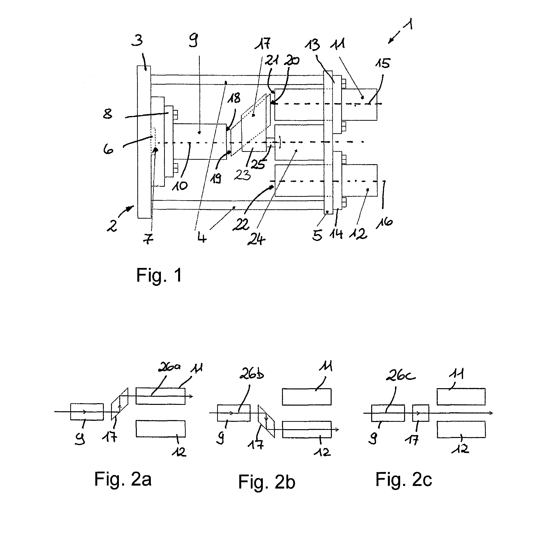
[0011]To change the fixed focal length, the output pupil of one of the afocal supplementary lenses is situated in front of this second prism face by appropriately swiveling the prism. One of the afocal supplementary lenses produces a larger fixed focal length when optically coupled to the base lens, and another afocal supplementary lens produces a smaller fixed focal length when coupled to the base lens. In this way the fixed focal length of the base lens is firmly established by the fixed focal lengths which are formed with the aid of the other supplementary lenses, thus allowing the fixed focal lengths to be changed from a wide-angle field of view to a close-range field of view, and vice versa, by rotating the prism in the same direction, and therefore, in a very rapid and efficient manner.

Problems solved by technology

In particular for space missions, not only are particularly stringent requirements imposed on such cameras with regard to the critical operating conditions, but in addition, such cameras having a low specific weight must also be automatically operable and low-maintenance.
Appropriate provision of adjustment mechanisms is complicated and susceptible to malfunction, in particular under the conditions prevailing in space.
Although multiple cameras having individual fixed focal lengths provide calibrated conditions for the individual focal lengths, with high measuring accuracy and reliability, they are rather costly and installation space-consuming due to the image capture and image processing electronics systems, together with corresponding optical sensors, which must be designed separately for each camera.

Method used


Image

  • Camera with pivotable prism
  • Camera with pivotable prism
  • Camera with pivotable prism

Examples


Embodiment Construction

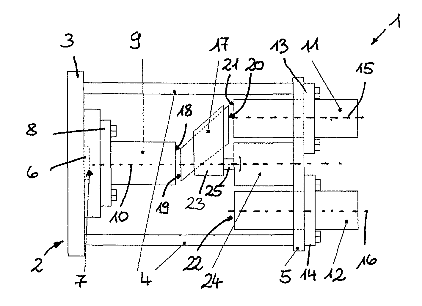
[0022]FIG. 1 schematically shows camera 1, which in the present case is a single-lens camera, having housing 2 which is formed from base plate 3, frame 4, and lens plate 5. CCD chip 6 having sensitive exposure surface 7, and which converts the optical signals striking exposure surface 7 and information into electrical signals, is fastened to base plate 3. A subsequent signal processing unit having an image memory, computation programs, and the like is not illustrated.

[0023]Base lens 9 is mounted over sensitive exposure surface 7 on base plate 3, calibrated with the aid of lens holder 8, optical axis 10 of the base lens being perpendicularly centered on exposure surface 7. Supplementary lenses 11, 12 are accommodated in lens plate 5, at a fixed distance from base lens 9, in each case parallel to optical axis 10 via an optical axis 15, 16, respectively, and situated equidistantly about optical axis 10 via lens holders 13, 14 at a calibrated distance from base lens 9.

[0024]With referen...


PUM


Abstract

A camera (1), in particular in a space vehicle, having a housing (2) which contains at least one optically sensitive exposure surface (7), and a base lens (9), having a first fixed focal length, connected thereto in each case, and which projects on the at least one exposure surface (7) and which is situated on a first optical axis (10) for the exposure surface (7). To provide the camera with various fields of view, in particular for the approach of two satellites toward one another over large distances, at least two afocal supplementary lenses (11, 12) which are each parallel with respect to their optical axes (15, 16) and spaced at a distance from the first optical axis (10) are situated in the housing (2), whose optical paths are alternately coupleable with the aid of a pivotable prism (17), to form further fixed focal lengths in an optical path of the base lens (9).

Description

[0001]This claims the benefit of German Patent Application DE 10 2010 017 057.7, filed May 21, 2010 and hereby incorporated by reference herein.[0002]The present invention relates to a camera, in particular in a space vehicle, having a housing which contains at least one optically sensitive exposure surface, and a base lens, having a first fixed focal length, connected thereto in each case and which projects on the at least one exposure surface and which is situated on a first optical axis for the exposure surface.BACKGROUND[0003]Cameras having interchangeable lenses of different fixed focal lengths and zoom lenses having variable focal lengths are well known. In particular for space missions, not only are particularly stringent requirements imposed on such cameras with regard to the critical operating conditions, but in addition, such cameras having a low specific weight must also be automatically operable and low-maintenance. Furthermore, such cameras should have a wide field of v...

Claims


Application Information

Patent Timeline
Patent Type & Authority Patents(United States)
IPC IPC(8): H04N5/225G02B26/08G02B26/10G02B26/12
CPCG02B15/06G03B17/14G03B35/08
Inventor KIRSCHSTEIN, STEFFENKOLB, FLORIANWUERL, RICHARDKRAEMER, DIRK
Owner JENA-OPTRONIK
Learn More