

Four-piece infrared single wavelength projection lens system
a single wavelength, infrared technology, applied in the field of lenses, can solve the problems of poor material transparency, inability to meet the 3d game focusing, and the focal length of the lens group will be changed, and achieve the effects of short length, high resolution, and large focal length
- Summary
- Abstract
- Description
- Claims
- Application Information
AI Technical Summary
Benefits of technology
Problems solved by technology
Method used
Image

Examples
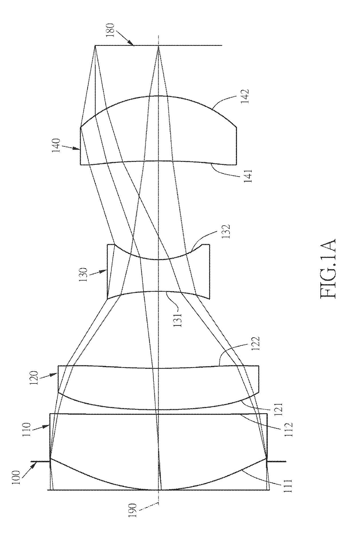
first embodiment
[0046]The equation for the aspheric surface profiles of the respective lens elements of the first embodiment is expressed as follows:
[0047]z=ch21+[1-(k+1)c2h2]0.5+Ah4+Bh6+Ch8+Dh10+Eh12+Gh14+…
[0048]wherein:
[0049]z represents the value of a reference position with respect to a vertex of the surface of a lens and a position with a height h along the optical axis 190;
[0050]c represents a paraxial curvature equal to 1 / R (R: a paraxial radius of curvature);
[0051]h represents a vertical distance from the point on the curve of the aspheric surface to the optical axis 190;
[0052]k represents the conic constant;
[0053]A B C D E G . . . : represent the high-order aspheric coefficients.
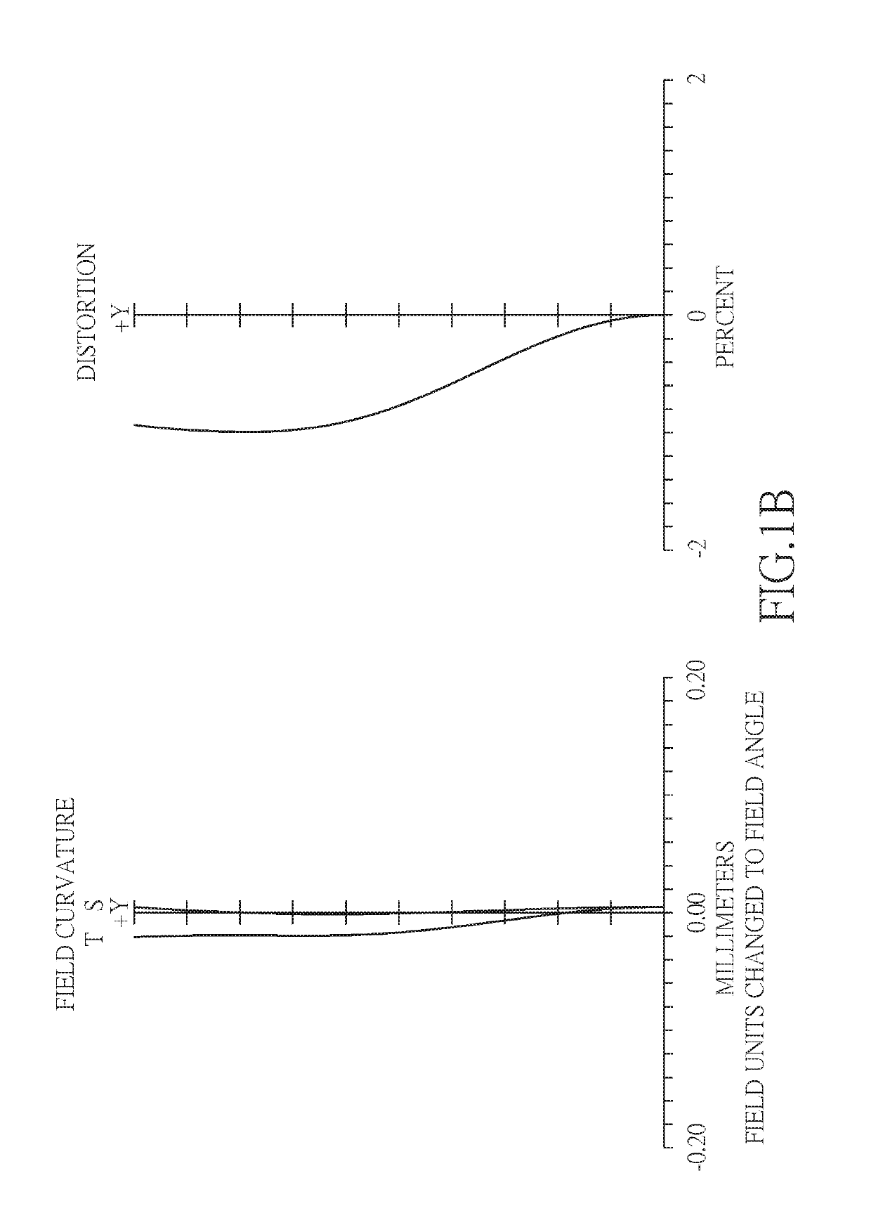
[0054]In the first embodiment of the present four-piece infrared single wavelength projection lens system, a focal length of the four-piece infrared single wavelength projection lens system is f, a f-number of the four-piece infrared single wavelength projection lens system is Fno, the four-piece infrared singl...
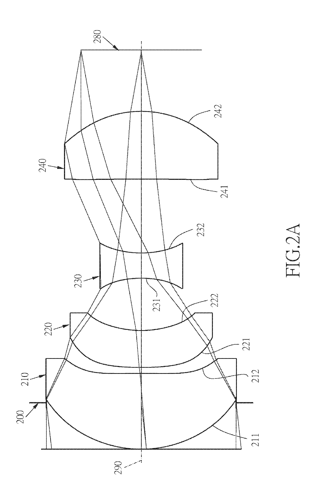
second embodiment
[0081]The detailed optical data of the second embodiment is shown in table 3, and the aspheric surface data is shown in table 4.
[0082]
TABLE 3Embodiment 2F(focal length) = 4.49 mm, Fno = 2.8, FOV = 12.8 deg.FocalsurfaceCurvature RadiusThicknessMaterialIndexAbbe #length0objectplane7001plane0.3862stopplane−0.3863Lens 10.967(ASP)0.628glass1.69453.21.344−11.955(ASP)0.0505Lens 22.521(ASP)0.307plastic1.63624.0−2.2160.840(ASP)0.4337Lens 3−0.958(ASP)0.209plastic1.63624.0−0.6880.798(ASP)0.6139Lens 4−24.441(ASP)0.561plastic1.63624.01.4510−0.867(ASP)0.50911Imageplanesourceplane
[0083]
TABLE 4Aspheric Coefficientssurface3456K:−4.7373E−01−5.0000E+02 1.1269E+01−5.4720E+00A: 5.8676E−03 4.8166E−01 4.5659E−01 6.1166E−01B: 1.5655E−01 1.3966E+00 2.8239E+00 2.3037E+00C: 5.8754E−02 1.9361E−01 1.2858E−01−4.2978E+00D: 9.8624E−02−3.5861E+00−6.7087E+00 3.7456E+01E:−3.8747E+00 2.2735E+02F: 4.6024E+01−6.9418E+02surface78910K: 3.5847E+00−2.3102E+00 1.3624E+02−7.7606E−01A:−2.0790E+00−1.1886E−01 ...
third embodiment
[0092]The detailed optical data of the third embodiment is shown in table 5, and the aspheric surface data is shown in table 6.
[0093]
TABLE 5Embodiment 3F(focal length) = 4.50 mm, Fno = 2.8, FOV = 12.8 deg.FocalsurfaceCurvature RadiusThicknessMaterialIndexAbbe #length0objectplane7001plane0.1952stopplane−0.1953Lens 11.240(ASP)0.600glass1.69453.21.214−1.989(ASP)0.0445Lens 22.749(ASP)0.312plastic1.63624.0−2.1260.842(ASP)0.4737Lens 3−1.101(ASP)0.223plastic1.63624.0−0.6080.586(ASP)0.5839Lens 4−8.292(ASP)0.573plastic1.63624.01.4210−0.804(ASP)0.50111Imageplanesourceplane
[0094]
TABLE 6Aspheric Coefficientssurface3456K:−7.9251E−01−4.1582E+01 1.2193E+01−8.4044E+00A:−2.5483E−02 2.0448E−01 4.0801E−01 2.1216E−02B: 3.5504E−03 5.9631E−03−2.8000E−01−1.3395E+00C: 4.2414E−02−1.5132E−01 2.1253E+00 7.7099E+00D:−1.1998E−01−4.8274E−03−3.8096E+00−1.1940E+01E: 3.9485E+00 1.1662E+00F: 0.0000E+00 0.0000E+00surface78910K: 8.2126E−01−1.1612E+01 1.4562E+02−7.8841E−01A:−2.8399E+00 6.0132E+00 2.805...
PUM
 Abstract
Description
Claims
Application Information