Apparatus and method for heating of hydrocarbon deposits by axial RF coupler
What is AI technical title?
AI technical title is built by Patsnap AI team. It summarizes the technical point description of the patent document.
a technology of axial rf coupler and hydrocarbon deposit, which is applied in the direction of subaqueous/subterranean adaption, insulation, and wellbore/well accessories, etc., can solve the problems of insufficient caprock for steam enhanced recovery, many bitumen resources may be too shallow, and water added to materials which requires a large amount of energy to remov
Active Publication Date: 2014-07-01
HARRIS CORP
View PDF147 Cites 9 Cited by
Summary
Abstract
Description
Claims
Application Information
AI Technical Summary
This helps you quickly interpret patents by identifying the three key elements:
Problems solved by technology
Method used
Benefits of technology
Benefits of technology
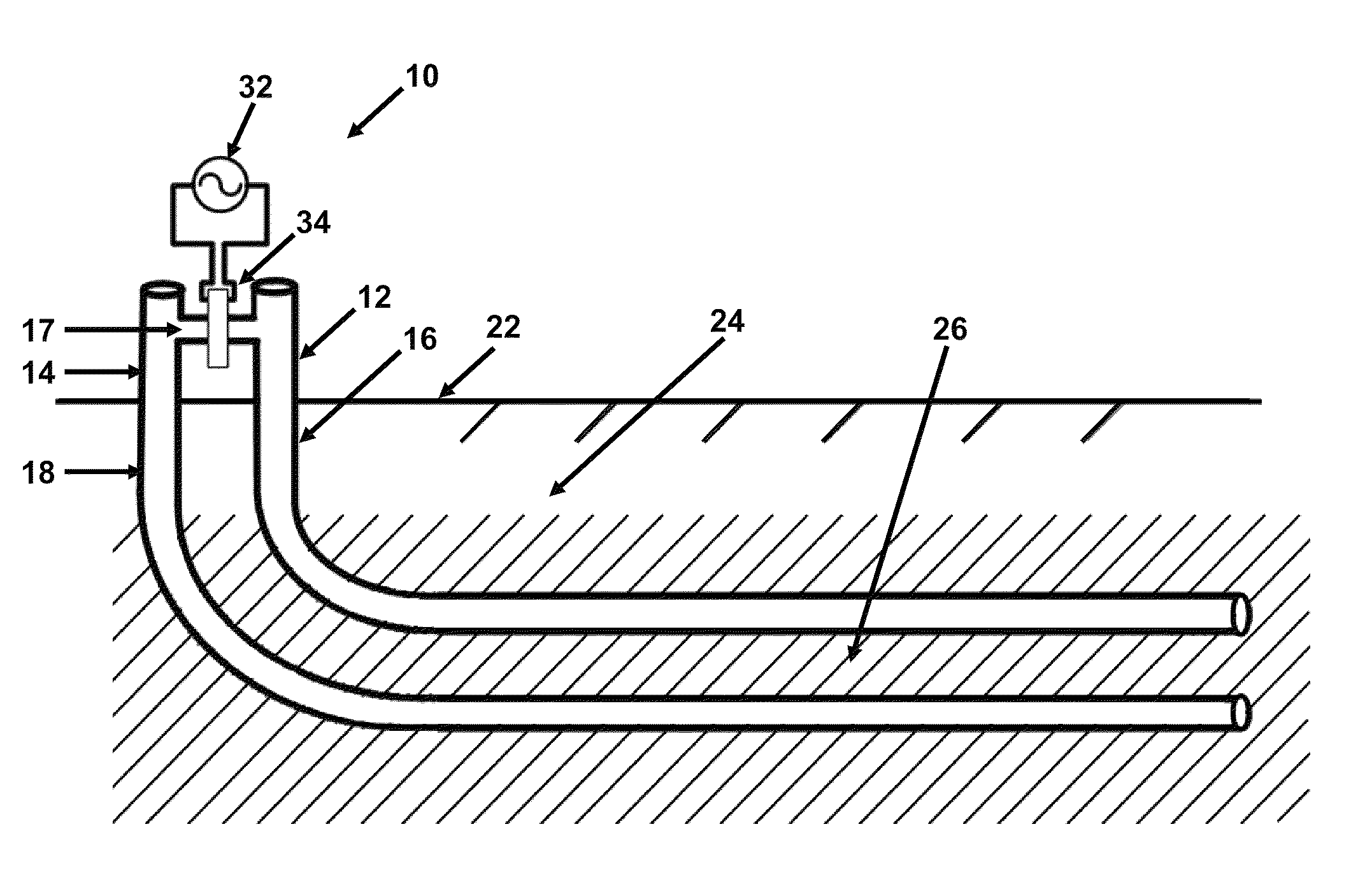
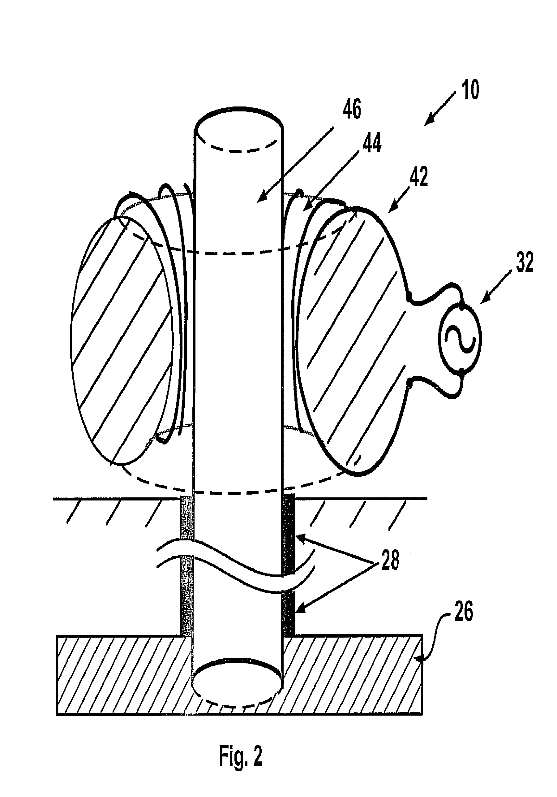
[0012]Yet another aspect of the invention includes use of an axial reactor that is adjacent to an element that emits RF energy to start and stop RF current flow through the emitting element.
Problems solved by technology
Among the disadvantages of SAGD is the addition of water to the materials which requires a large amount of energy to remove.
Many bitumen resources may be too shallow or with insufficient caprock for steam enhanced recovery.
Thus, prior systems for heating subsurface heavy oil bearing formations by RF has generally relied on specially constructed and structurally complex RF emitting structures that are positioned within a well.
Method used
Image
Click on the blue label to locate the original text in one second.
Reading with bidirectional positioning of images and text.
Examples
Embodiment Construction
[0027]The present invention will now be described more fully hereinafter with reference to the accompanying drawings, in which one or more embodiments of the invention are shown. This invention may, however, be embodied in many different forms and should not be construed as limited to the embodiments set forth herein. Rather, these embodiments are examples of the invention, which has the full scope indicated by the language of the claims. Like numbers refer to like elements throughout.
[0028]RF heating may provide for extraction of otherwise stranded resources as it may provide heating at reduced underground pressures. RF electromagnetic heating may comprise the application of up to three separate RF energies; electric fields, magnetic fields and electric currents. Heavy oil formations frequently contain in situ liquid water providing a good susceptor for RF heating. For instance, the Athabasca region oil sands of Canada may have electrical conductivities between about 0.002 to 0.15 ...
PUM
Abstract
An apparatus for heating a hydrocarbon deposit that is susceptible to RF heating by coupling a linear conductive element that extends into the material to a source of RF power. The apparatus includes a source of RF power connected to driving winding that extends around a magnetic core loop and the magnetic core loop extends around the RF conductive linear element. One or more apparatus may be used to couple RF energy to conductive elements that extend into a hydrocarbon deposit to achieve a desired RF current within the element. RF energy may be coupled to conductive elements that are adjacent to each other within a hydrocarbon deposit to create a desired region of heating within the hydrocarbon deposit. The magnetic core loop may start and stop the RF energy to position heating.
Description
CROSS REFERENCE TO RELATED APPLICATIONS[0001]This specification is related to[0002]U.S. patent application Ser. No. 12 / 878,774 filed Sep. 9, 2010, Ser. No. 12 / 903,684 filed Oct. 13, 2010, Ser. No. 12 / 820,977 filed Jun. 22, 2010, Ser. No. 12 / 835,331 filed Jul. 13, 2010, and Ser. No. 12 / 886,338 filed Sep. 20, 2010, filed on or about the same date as this specification, each of which is hereby incorporated herein in its entirety by reference here.[0003]This specification is also related to[0004]U.S. patent application Ser. No. 12 / 396,284 filed Mar. 2, 2009, Ser. No. 12 / 396,247 filed Mar. 2, 2009, Ser. No. 12 / 396,192 filed Mar. 2, 2009, Ser. No. 12 / 396,057 filed Mar. 2, 2009, Ser. No. 12 / 396,021 filed Mar. 2, 2009, Ser. No. 12 / 395,995 filed Mar. 2, 2009, Ser. No. 12 / 395,953 filed Mar. 2, 2009, Ser. No. 12 / 395,945 filed Mar. 2, 2009 and Ser. No. 12 / 395,918 filed Mar. 2, 2009, each of which is hereby incorporated herein in its entirety by reference.STATEMENT REGARDING FEDERALLY SPONSORED ...
Claims
Application Information
Patent Timeline
Application Date:The date an application was filed.
Publication Date:The date a patent or application was officially published.
First Publication Date:The earliest publication date of a patent with the same application number.
Issue Date:Publication date of the patent grant document.
PCT Entry Date:The Entry date of PCT National Phase.
Estimated Expiry Date:The statutory expiry date of a patent right according to the Patent Law, and it is the longest term of protection that the patent right can achieve without the termination of the patent right due to other reasons(Term extension factor has been taken into account ).
Invalid Date:Actual expiry date is based on effective date or publication date of legal transaction data of invalid patent.

