IQ mismatch cancellation

a technology of iq mismatch and cancellation, applied in the field of iq mismatch cancellation, can solve problems such as non-linearity of amplification

Inactive Publication Date: 2005-05-24
INTEL CORP
View PDF7 Cites 47 Cited by
  • Summary
  • Abstract
  • Description
  • Claims
  • Application Information

AI Technical Summary

Problems solved by technology

These inaccuracies may cause the transmitter to interfere with signals on carrier frequencies allocated to other transmitters and therefore shoul

Method used


Image

  • IQ mismatch cancellation
  • IQ mismatch cancellation
  • IQ mismatch cancellation

Examples


Embodiment Construction

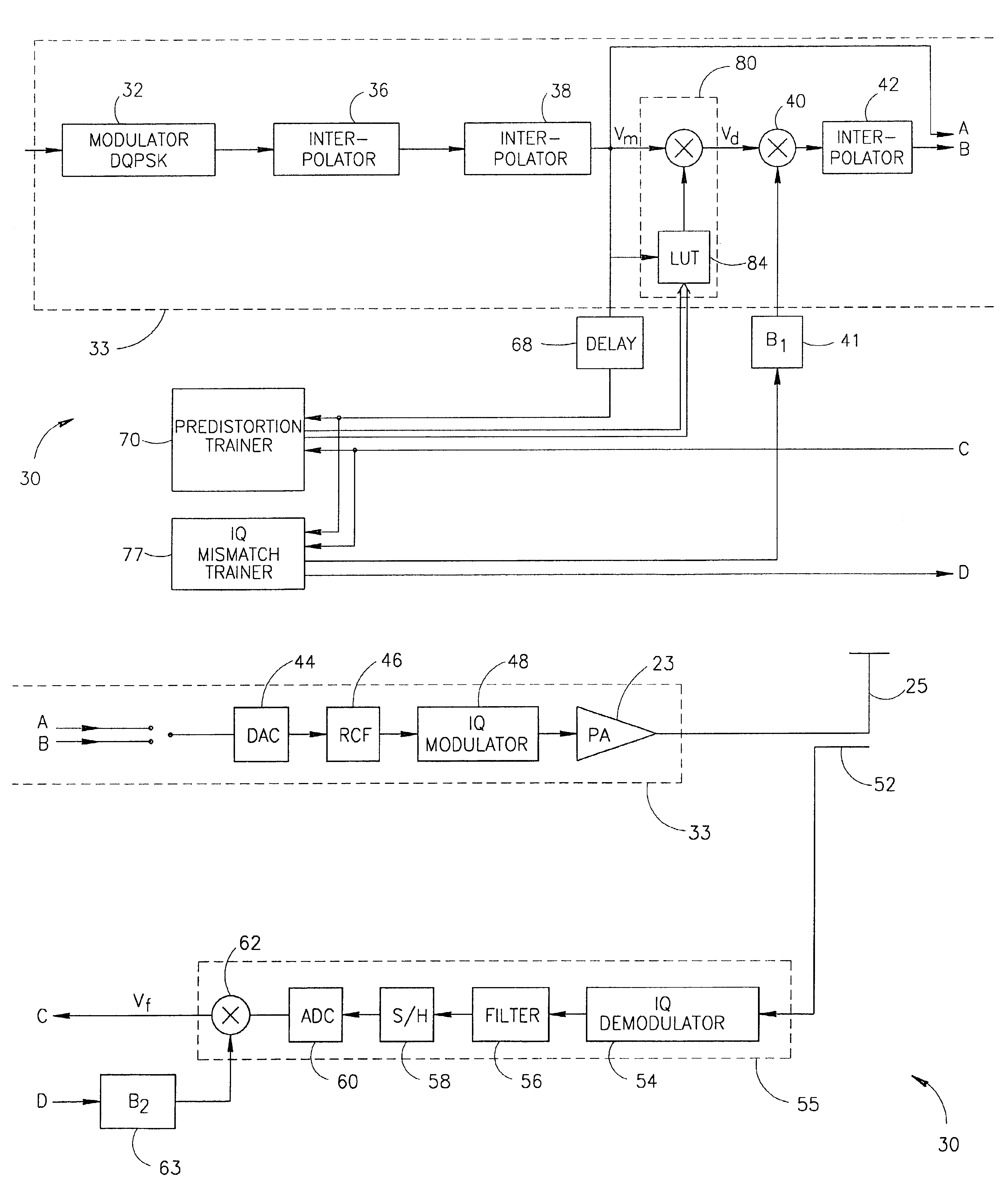
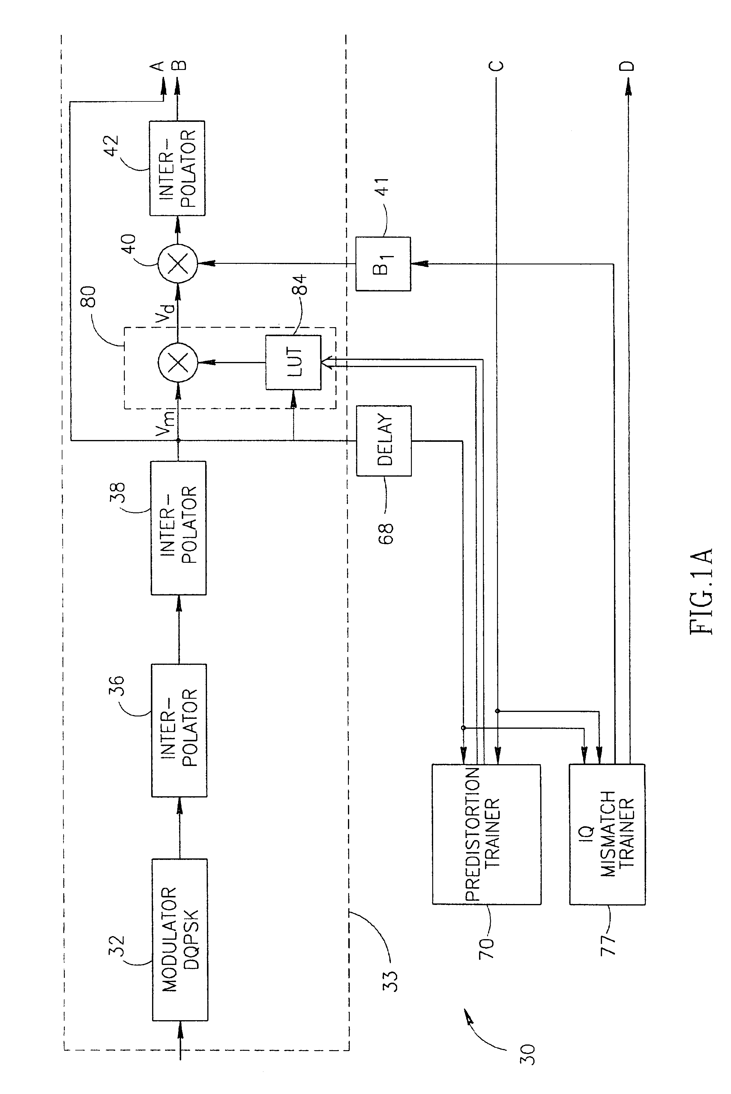
[0010]FIGS. 1A and 1B are a schematic block diagram of a transmitter 30, in accordance with an exemplary embodiment of the present invention. Transmitter 30 comprises a transmission modulation path 33 which receives bits and shapes them for transmission over an antenna 25. In an exemplary embodiment of the invention, modulation path 33 includes a π4

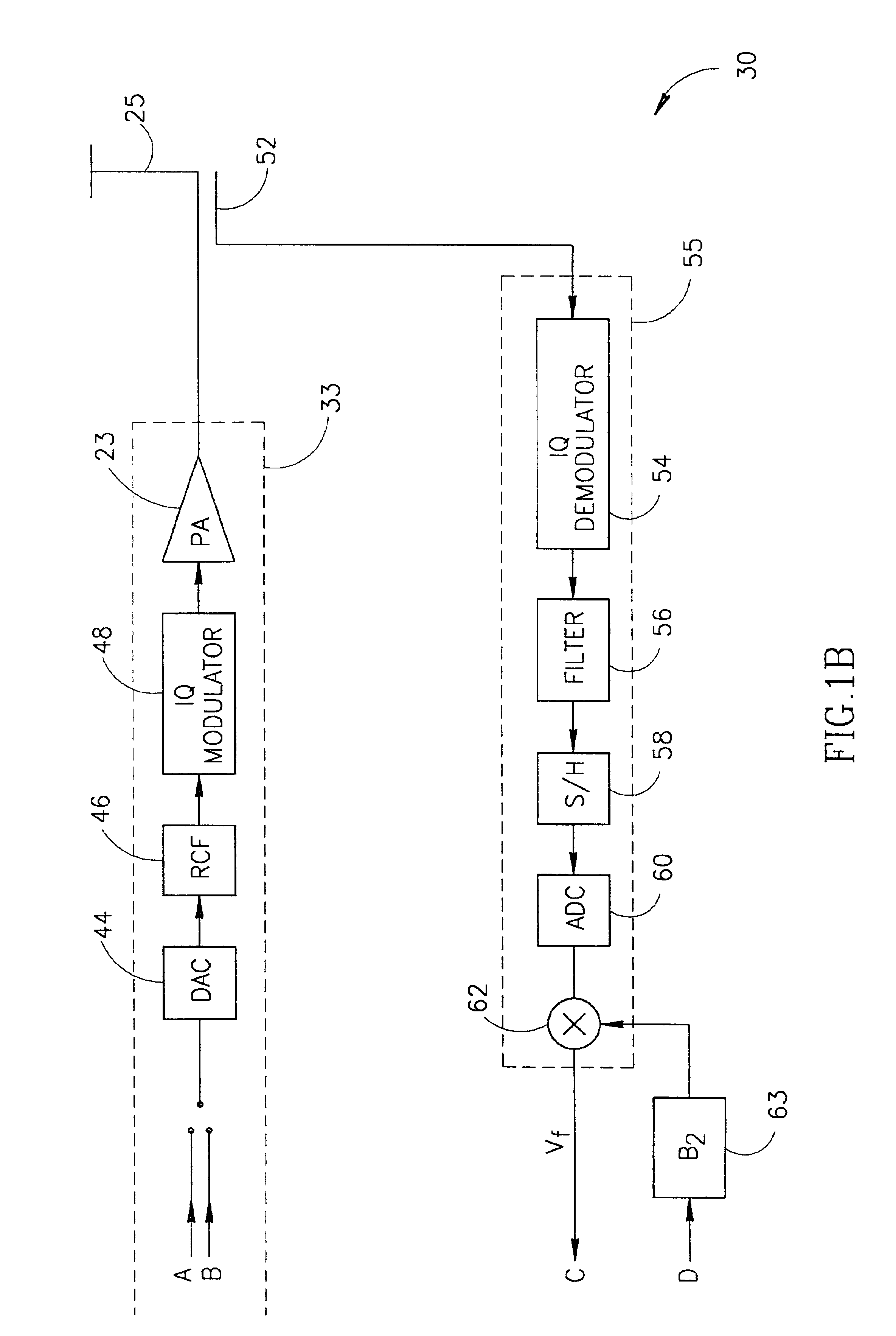
DQPSK (Differential Quadrature Phase Shift Keying) modulator 32, a first interpolator 36, a second interpolator 38, a predistorter 80, a mismatch multiplier 40, a third interpolator 42, a digital to analog converter (DAC) 44, a reconstruction filter (RCF) 46, an IQ modulator 48 and a power amplifier 23.

[0011]A directional coupler 52 senses the signals transmitted by amplifier 23 and passes them through a reverse conversion unit 55 which substantially reverses the operation of an ending portion of modulation path 33, bringing the signals back to a state in which they can be compared to the signals provided by second interpolator 38. In som...


PUM


Abstract

A method of assigning values to parameters for IQ mismatch cancellation. The method includes providing values to a processing path of a communication device, passing the provided values through an IQ modulator, at least one non-linear element and an IQ demodulator, to produce distorted values, and estimating at least one parameter for cancellation of IQ mismatch effects of the communication device responsive to the provided values and to the distorted values.

Description

BACKGROUND OF THE INVENTION[0001]Many transmitters transmit digital information values that are generated in base band. The base band digital values are modulated onto a carrier high frequency signal and the combined signal is amplified before its transmission. The base band values may be complex values having real and imaginary components which arc traditionally referred to as I and Q components, respectively. In the modulation of the base band signal and amplification of the modulation signal, inaccuracies are introduced. These inaccuracies may cause the transmitter to interfere with signals on carrier frequencies allocated to other transmitters and therefore should be at least partially canceled by the transmitter.[0002]One of these inaccuracies, which is due mainly to an IQ modulator of the transmitter, is referred to as IQ mismatch which is generally modeled by the following equation: V_q=(IqQq)=[cos⁡(φ)sin⁡(-φ)b⁢ ⁢sin⁡(-φ)b⁢ ⁢cos⁡(φ)]⁢ ⁢(IdQd)(1)in which Id, Qd are the real an...

Claims


Application Information

Patent Timeline
IPC IPC(8): H04L25/03H04K1/02H04L25/49H04L27/36H04L27/38
CPCH04L27/364H04L27/3863H04L27/368
Inventor YELLIN, DANIELFRANCOS, AMIR
Owner INTEL CORP
Why Eureka
Try Eureka