
Dynamically configurable logic gate using a non-linear element

a nonlinear element and logic gate technology, applied in the field of dynamic computing, can solve the problems that computing modules, however, can be reconfigured to a limited degree, and the functionality of logic gates or memory latches cannot be dynamically changed once the component is fabricated, so as to achieve the effect of fewer components and less power consumption

Active Publication Date: 2008-11-18
CHAOLOGIX INC
View PDF15 Cites 43 Cited by
  • Summary
  • Abstract
  • Description
  • Claims
  • Application Information

AI Technical Summary

Benefits of technology

"The present invention is about a new type of logic gate that can be dynamically configured. It includes an input summer that combines two input signals to create a summed input signal, which is then processed by a nonlinear element to produce a nonlinear output signal. This nonlinear output signal can be used to create different logic gates by adjusting the input signals. The logic gate has low power consumption, requires fewer components, and can be designed for digital or analog use. Additionally, the invention provides an array of configurable logic blocks with configurable routing. Overall, the invention offers a flexible and efficient way to create custom logic circuits."

Problems solved by technology

Within static computing systems, the various hardware components of the computing system cannot be reconnected or reconfigured during operation.
For example, the functionality of hardware components such as logic gates or memory latch cannot be dynamically changed once the component is fabricated.
Some computing modules, however, can be reconfigured to a limited degree.
For example, field programmable gate arrays (FPGAs) provide a limited degree of flexibility with respect to reconfiguration.
Such efforts have been limited to simply redirecting signal flows or “rewiring” devices or components such as FPGA'S.
Chua's circuit although easy to implement with off the shelf components, it is not feasible to manufacture using integrated circuit technology because the necessary inductors and capacitors consume too much circuit area and the large number of operational amplifiers necessitate numerous transistors.
Moreover, integrated circuits based on Chua's circuit are often very difficult to control because the component values are very sensitive.

Method used


Image

  • Dynamically configurable logic gate using a non-linear element
  • Dynamically configurable logic gate using a non-linear element
  • Dynamically configurable logic gate using a non-linear element

Examples


first embodiment

[0055 of Dynamically Configurable Logic Gate

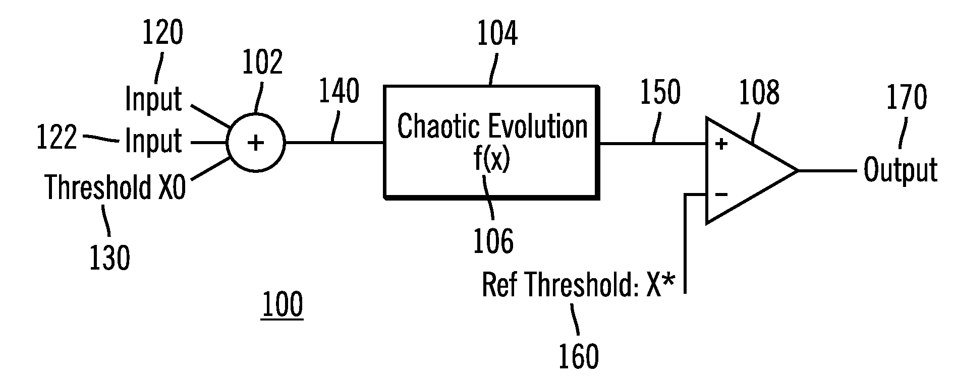
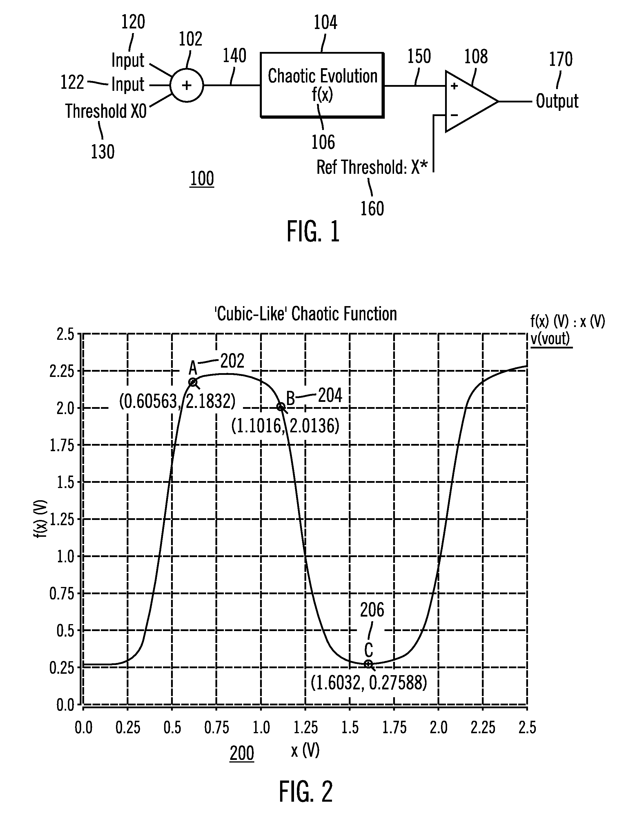
[0056]Turning now to FIG. 1, shown is a schematic diagram illustrating one embodiment of a high-level circuit architecture 100 for a dynamically configurable logic gate, according to the present invention. In this implementation multiple chaotic evolutions are not necessary, and only a single chaotic evolution is necessary between the input and the output threshold circuit. By implementing only a single chaotic evolution, this greatly simplified the circuit to an input summer or input adder 102, the nonlinear element or chaotic circuit 106, and an output comparator 108.

[0057]As shown in FIG, 1, the dynamically configurable logic gate includes an input summer or input adder 102. The input adder 102 receives three signals: an input first signal 120; a second input signal 122; and a first threshold signal 130. The input adder 102 combines the three signals 120, 122, and 130 to form a summed signal 140, which is the input into the nonlinear el...

second embodiment

[0062 of Dynamically Configurable Logic Gate

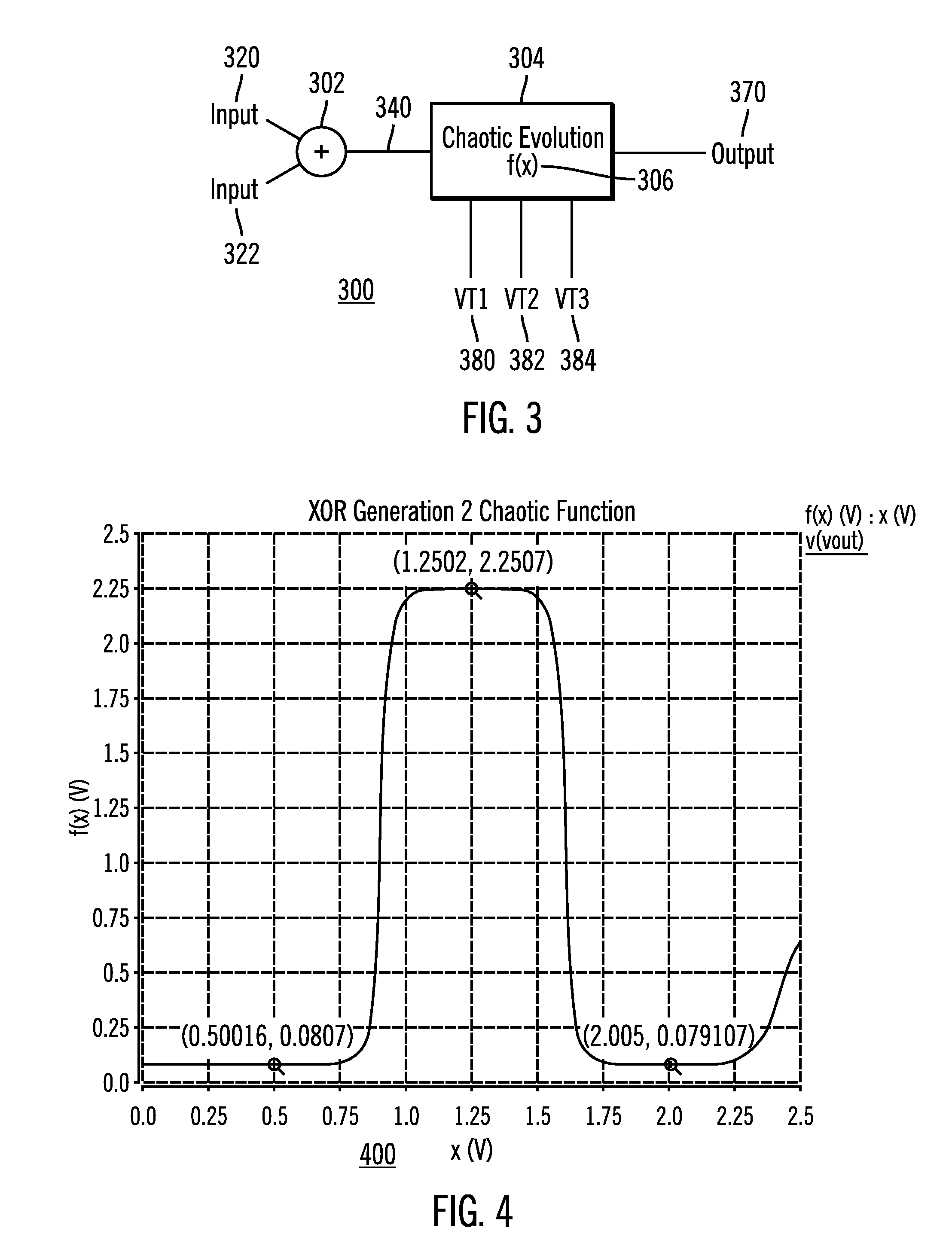
[0063]FIG. 3 is a schematic diagram illustrating another embodiment of a high level circuit architecture 300 for a dynamically configurable logic gate, according to the present invention. An input summer or input adder 302 accepts two input signals 320 and 322 to form a summed signal 340. The summed signal is the input to the nonlinear or chaotic element 304 with nonlinear function 306 which is configured to apply the nonlinear function 306 to the summed signal 340 to produce a nonlinear output signal 370. The nonlinear function is 306 and / or the dynamic regions upon which the summed signal 340 is mapped is changed in response to change of at least one of the reference signals 380, 382, and 384. The nonlinear output signal 370 corresponds to a plurality of different logic gates responsive to adjusting one or more of the reference signals 380, 382, and 384 and / or the nonlinear function 306.

[0064]In this circuit architecture 300 the referenc...

third embodiment

[0069 of Dynamically Configurable Logic Gate

[0070]In this embodiment, the power is further reduced using an all digital CMOS implementation for the dynamically configurable logic gate. The major elements with the other embodiments of the dynamically configurable logic gate are present in this embodiment. The input summer provides the count of the inputs represented as a state space. The configuration operates as the threshold mechanism to change the mapping of the input state space to the chaotic evolution. The nonlinear or chaotic evolution provides the non-linear function to convert to the output. Because of the full digital nature, the static power is reduced to substantially zero.

[0071]FIG. 5 is a schematic diagram illustrating another embodiment of a high level circuit architecture 500 for a dynamically configurable logic gate, according to the present invention. An input summer or input adder 502 accepts three input signals 520, 522 and 524 to form a digital state output signa...


PUM


Abstract

A dynamically configurable logic gate includes an input summer for receiving a first input signal and a second input signal to generate a summed input signal. Further the dynamically configurable logic gate includes a nonlinear element that applies a nonlinear function to the summed input signal to produce a nonlinear output signal. The dynamically configurable logic gate output signal corresponds to one of a plurality of different logic gates responsive to adjusting the summed input signal and / or the nonlinear function. In another embodiment, the dynamically configurable logic gate includes feedback to one of the inputs. The dynamically configurable logic gate receives the two inputs and operates as one of a plurality of different logic gate types so as to produce an output signal that corresponds to a memory latch according to a selection of the control signal. An array structure of dynamically configurable logic elements is also disclosed.

Description

FIELD OF THE INVENTION[0001]The present invention generally relates to the field of dynamic computing and, more particularly, to configurable computing architecture for logic gates using nonlinear elements.BACKGROUND OF THE INVENTION[0002]Conventional computing systems rely on static combination of logic gates to implement one or more predefined Boolean algebraic functions and / or memory. Within static computing systems, the various hardware components of the computing system cannot be reconnected or reconfigured during operation. For example, the functionality of hardware components such as logic gates or memory latch cannot be dynamically changed once the component is fabricated.[0003]Some computing modules, however, can be reconfigured to a limited degree. For example, field programmable gate arrays (FPGAs) provide a limited degree of flexibility with respect to reconfiguration. Such efforts have been limited to simply redirecting signal flows or “rewiring” devices or components s...

Claims


Application Information

Patent Timeline
Patent Type & Authority Patents(United States)
IPC IPC(8): H03K19/173
CPCH03K19/173H03K3/037
Inventor KIEL, STEVEN LEEKRENING, DOUGLAS NORMANLEHMAN, LARK EDWARDSCHNEIDERWIND, MICHAEL JOSEPH
Owner CHAOLOGIX INC
Learn More