Power supply system including panel with safety release

a technology of power supply system and safety release, which is applied in the direction of electrical devices, coupling device connections, transportation and packaging, etc., can solve the problems of standard plug operation that does not provide automatic power shutoff and breakaway protection, and achieves sufficient structural integrity, minimizes the exposure of ports, and ensures the safety of the system and of any user

Active Publication Date: 2014-07-01
ATLANTIC DYNAMICS LLC
View PDF67 Cites 41 Cited by
  • Summary
  • Abstract
  • Description
  • Claims
  • Application Information

AI Technical Summary

Benefits of technology

[0011]It is an object of the present invention to provide a power supply system that is suitable for use with mobile systems. It is also an object of the present invention to provide such a power supply system that reduces the need to operate an engine or motor to supply energy to the mobile system when the mobile system is in a location where it is desirable to tap into a power grid to maintain one or more functions. It is also an object of the present invention to provide such a power supply system that is configured to minimize unsafe use or operation thereof.
[0013]The safety ejection subsystem includes a self-ejecting latch that is securely attached to the plug end of the power cord. The latch is also attached to a tension line that terminates with secure fastening to the power cord, such as by weaving it into the power cord's insulative layer or layers. The safety ejection subsystem part of the present invention is configured to ensure that the cord will release from the wall receptacle in a situation when the user neglects to intentionally pull the power cord from the receptacle prior to the mobile system departing the location where the circuit panel is located. For example, if the mobile system powered via the circuit panel is a refrigerated trailer connected to a tractor and the driver fails to pull the power cord from the wall receptacle, the safety ejection subsystem exerts a pulling force at the plug end of the power cord as the cord itself is being pulled by the trailer. The self-ejecting latch is of sufficient structural integrity that it will only pull the cord at the plug / receptacle interface and not somewhere intermediate on the power cord itself, which could otherwise result in live wire exposed and still joined to the circuit panel receptacle. The electrical components that move with the mobile system are no longer active when disconnection from the circuit panel occurs. Likewise, upon disengaging, the power to the circuit panel is cut based on a complicated connector arrangement that ensures there is no power at the receptacle when the plug is inserted and when the plug is removed. Also, an “on” switch must be engaged before charges pass to the receptacle. The connector, which may be a six-pin connector or other complicated connector, is arranged to ensure that only one satisfactory interfacing of plug to receptacle exists for power to pass from the circuit panel to the power cord. The six-pin connector configuration described herein provides a complicated connection arranged in a way that eliminates the possibility of a powered faulty connection between the power cord and the wall receptacle socket. It is to be understood that other numbers of pins and associated ports or pinholes may be employed without deviating from the invention. Standard plug operations do not use complicated pin combinations, thereby allowing foreign objects and faulty plugs to receive power. Standard plug operations do not provide automatic power shutoff and breakaway protection. The present invention provides such safety features. Further, an insulated and weatherproof hinged sealing cover of the socket substantially minimizes the exposure of the ports of the wall receptacle socket to any liquid or human contact. Two embodiments of the invention are described herein. A first embodiment for which the power cord is connected from a device to be powered to the power supply and a second embodiment for which the power cord is hardwired to the power supply and the device to be powered is connected to the power cord but needs no power cord itself.
[0014]The configuration of the power supply system of the present invention enables users to power mobile systems with grid power through means that may be accessible in otherwise remote locations, or at least in locations where it may be difficult to power mobile systems in a conventional manner. This invention thereby provides access to power sources while minimizing or eliminating the need to operate an engine or motor to supply energy to the mobile system while also ensuring that safety of the system and of any user is not compromised. These and other advantages of the present invention will be more fully understood upon review of the following detailed description, the accompanying drawings, and the appended claims.

Problems solved by technology

Standard plug operations do not provide automatic power shutoff and breakaway protection.

Method used


Image

  • Power supply system including panel with safety release
  • Power supply system including panel with safety release
  • Power supply system including panel with safety release

Examples


first embodiment

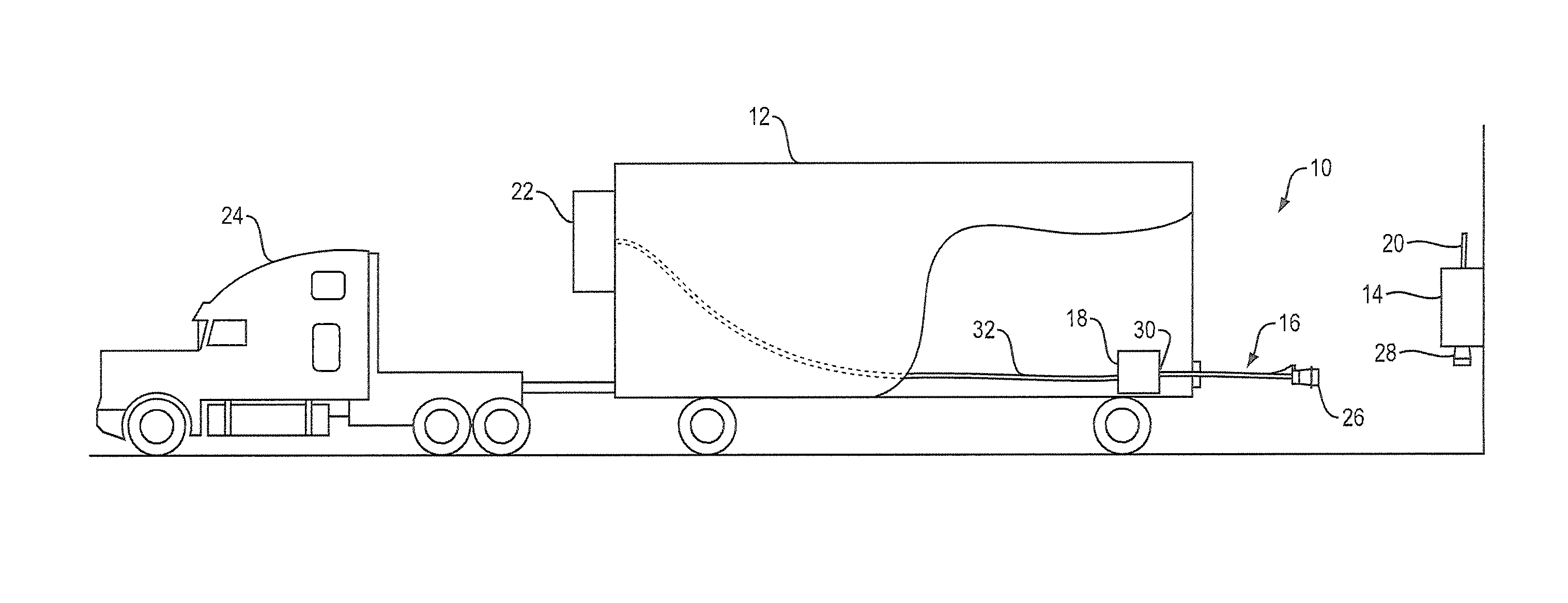
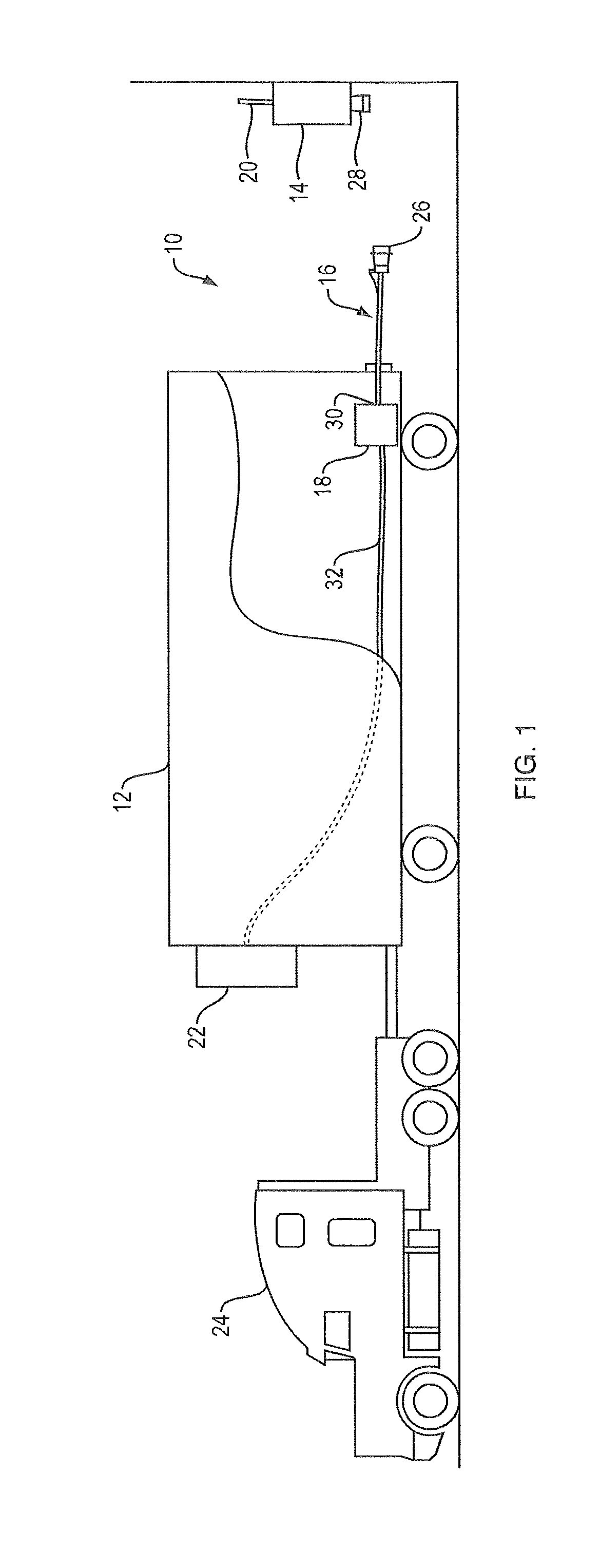
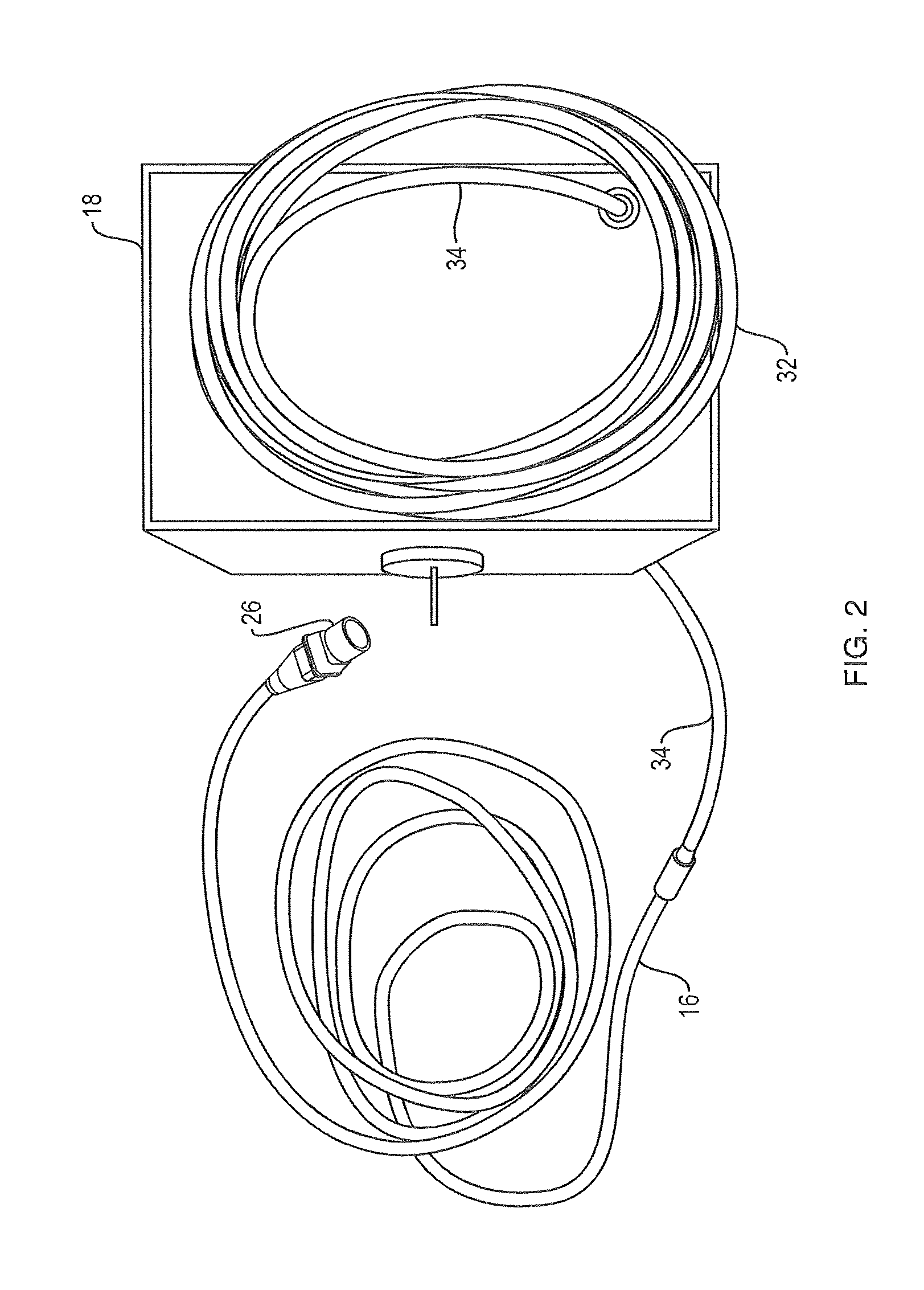
[0029]A power supply system 10 of the present invention is shown associated with a refrigerated trailer 12 in FIG. 1. The power supply system 10 includes a safety circuit panel 14, a power cord 16 and an optional cord storage box 18. The safety circuit panel 14 is coupled to grid power through panel cord 20, which provides electricity into the panel 14 for the purpose of connection to a power conductor, such as one or more wires of power cord 16. In the example usage represented in FIG. 1, the circuit panel 14 may be used to supply power to an engine of a refrigeration unit 22 of the trailer 12. In this way, the refrigeration unit 22 may be operated to keep the contents of the trailer 12 temperature controlled using grid power rather than power from the engine of the refrigeration unit 22, which itself must be powered by a tractor 24 used to haul the trailer 12. The power cord 16 includes a first end 26 for releasable connection to a wall receptacle 28 of the circuit panel 14 and a ...

second embodiment

[0041]A power supply system 100 of the present invention is shown associated with a refrigerated trailer 12 in FIG. 7. The power supply system 100 includes a safety circuit panel 114, a power cord 116 and a power plug 118 that may be contained in a containment box 119, shown in FIG. 9. The length of the power cord 116 is selectable. The power plug 118 is configured to ensure that current moves to the trailer 12 when it and the power cord 116 are aligned and connected in a specific way. In this embodiment, the power plug 118 includes a six-pin face that engages with a six-pinhole plug face 150 of the power cord 116. Current only moves when the two are properly aligned and engaged. The trailer 12 may include the optional cord storage box 18. The safety circuit panel 114 is coupled to grid power through panel cord 20, which provides electricity into the panel 114 for the purpose of connection to a power conductor, such as one or more wires of the power cord 116. In the example usage re...


PUM


Abstract

A power supply system for use with a power source. The system includes a safety circuit panel with a safety circuit and a power cable with a safety release in the form of a safety ejection subsystem. The safety ejection subsystem includes a latch connected to the wall receptacle connector of the power cable and a tension line connected to the latch and to the power cable. When the power cable is placed in tension, such as when the power cable has not been disconnected from the wall receptacle in the ordinary way, the safety ejection subsystem forces the disconnection of the power cable from a plug, thereby ensuring that no live wiring is exposed to the environment.

Description

CROSS REFERENCE TO RELATED APPLICATIONS[0001]This application is a continuation-in-part of, and claims a priority benefit to, pending U.S. patent application Ser. No. 13 / 631,294, filed Sep. 28, 2012, entitled POWER SUPPLY SYSTEM INCLUDING PANEL WITH SAFETY RELEASE. This application is also a nonprovisional of, and claims a priority benefit to U.S. provisional patent application Ser. No. 61 / 752,044, filed Jan. 14, 2013, entitled POWER SUPPLY SYSTEM INCLUDING PANEL WITH SAFETY RELEASE. The applications are owned by a common assignee. The priority applications are incorporated in their entirety herein by reference.BACKGROUND OF THE INVENTION[0002]1. Field of the Invention[0003]The present invention relates power supply systems including supply panels. More particularly, the present invention relates to power supply systems accessible by a variety of power users including, but not limited to, mobile systems such as vehicles and other transportation equipment. Still more particularly, th...

Claims


Application Information

Patent Timeline
Patent Type & Authority Patents(United States)
IPC IPC(8): H01R13/62
CPCH01R13/6275H01R13/62H01R2201/26H02J7/00B60L3/04B60L11/18H01R13/633B60D1/62
Inventor LAMB, SCOTT, D.
Owner ATLANTIC DYNAMICS LLC
Why Eureka
Try Eureka