Projector

a projector and projector technology, applied in the field of projectors, can solve the problems of increasing the power consumption of the projector, affecting the performance of the projector, and affecting the operation of the projector, so as to prevent the deterioration of the parts

Inactive Publication Date: 2014-07-01
SEIKO EPSON CORP
View PDF17 Cites 4 Cited by
  • Summary
  • Abstract
  • Description
  • Claims
  • Application Information

AI Technical Summary

Benefits of technology

[0010]An advantage of some aspects of the invention is to provide a projector that can project a image in such a way that the image appears bright while preventing deformation of an electrode.
[0013]When the deteriorating state progresses, the fusibility of the electrode is reduced, which may cause deformation of the electrode. According to the aspect of the invention, by controlling the discharge lamp driving section so that the ratio of the absolute value of the drive current in the second period to the absolute value of the drive current in the first period is increased with the progress of the deteriorating state of the discharge lamp, it is possible to increase the fusibility of the electrode in the second period in particular. This makes it possible to prevent deformation of the electrode.
[0014]Moreover, according to the aspect of the invention, since the control section controls the discharge lamp driving section so that the absolute value of the drive current becomes relatively small in the first period and relatively large in the second period, it is possible to realize a projector that can project a image in such a way that the image appears bright. Furthermore, since the control section controls the discharge lamp driving section so that the ratio of the absolute value of the drive current in the second period to the absolute value of the drive current in the first period is increased with the progress of the deteriorating state of the discharge lamp, it is possible to prevent a reduction in the drive current in the second period. Therefore, it is possible to prevent a reduction in the brightness associated with the progress of the deteriorating state of the discharge lamp.
[0016]As a result, the current with the same polarity flows for a longer period of time in the second period. Therefore, it is possible to increase the fusibility of the electrode in the second period. This makes it possible to prevent deformation of the electrode.
[0018]As a result, the current with the same polarity flows for a shorter period of time in the first period. Therefore, a low-temperature state continues for a shorter period of time in the first period. This makes it possible to prevent deformation of the electrode.
[0020]As a result, it is possible to prevent deterioration of the parts forming the discharge lamp driving section.

Problems solved by technology

However, JP-A-2009-237302 describes that if the intensity of the light source is simply varied, an electrode of the discharge lamp will wear out significantly.
Moreover, when crosstalk by which the image for the right eye enters the left eye or the image for the left eye enters the right eye occurs, the observer loses the sense of viewing the stereoscopic image.
However, this increases the power consumption of the projector or accelerates the deterioration of peripheral parts associated with the increase in drive power.
Moreover, if control to reduce the brightness of the discharge lamp in a period in which both active shutters are closed and increase the brightness of the discharge lamp in a period in which one of the active shutters is opened is performed to make the image appear bright, the temperature of the electrode of the discharge lamp is reduced in a period in which the brightness of the discharge lamp is reduced, resulting in inadequate fusibility of the tip of the electrode.
This may cause deformation of the electrode.
When the electrode is deformed, there is a possibility of, for example, the occurrence of flicker.
In particular, when a drive current of the discharge lamp becomes smaller with the progress of a deteriorating state of the discharge lamp, the brightness of the discharge lamp is reduced and the fusibility of the tip of the electrode becomes inadequate, which makes the electrode tend to be deformed.
When the deteriorating state progresses, the fusibility of the electrode is reduced, which may cause deformation of the electrode.

Method used


Image

  • Projector
  • Projector
  • Projector

Examples


Embodiment Construction

[0037]Hereinafter, a preferred embodiment of the invention will be described in detail by using the drawings. It should be understood that the embodiment described below is not meant to limit unduly the scope of the invention claimed in the appended claims in any way, and all the configurations described below are not always necessary requirements of the invention.

1. Optical System of a Projector According to the Embodiment

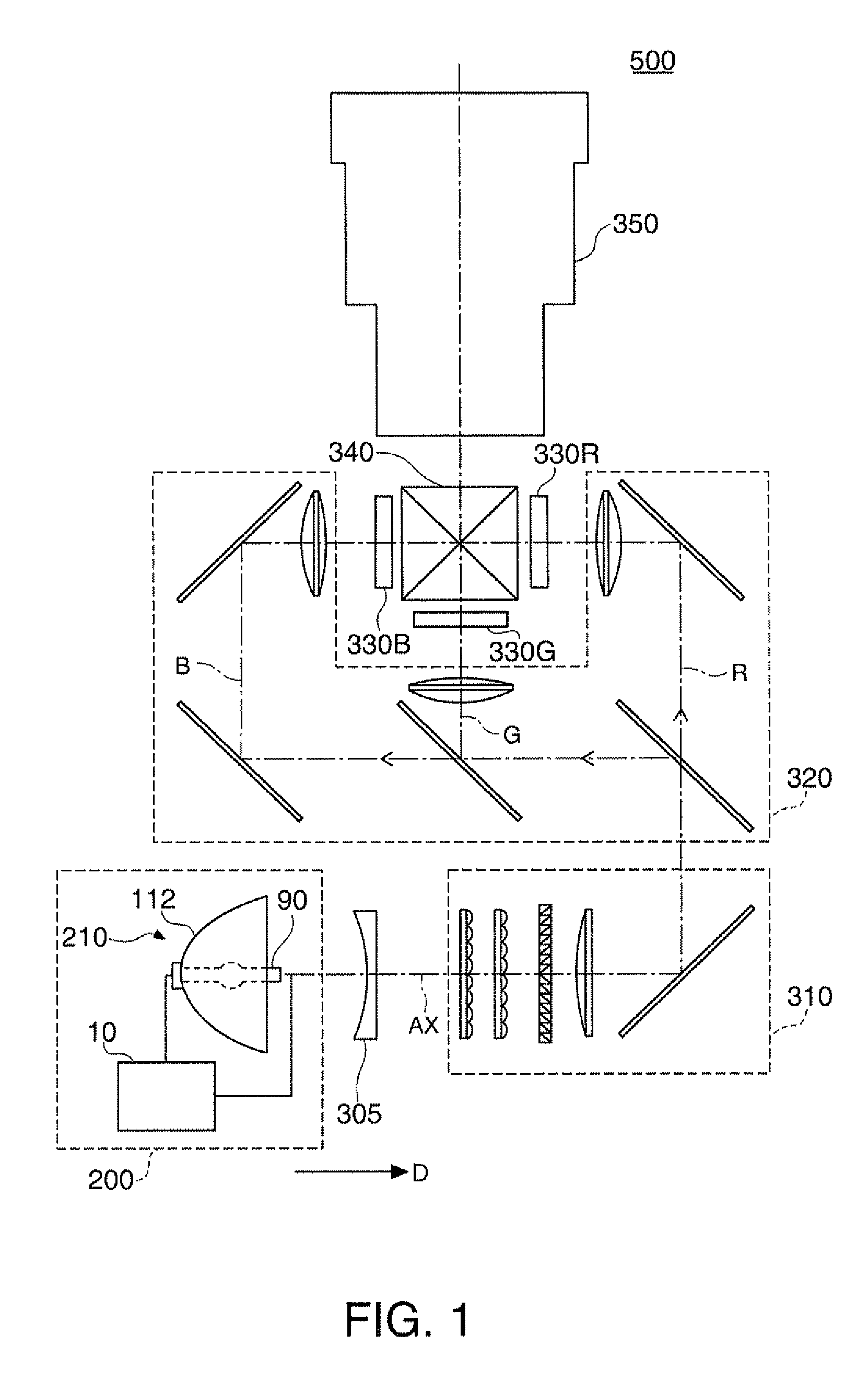
[0038]FIG. 1 is an explanatory diagram showing an optical system of a projector 500 according to the embodiment. The projector 500 has a light source device 200, a parallelizing lens 305, an illumination system 310, a color separation system 320, three liquid crystal light valves 330R, 330G, and 330B, a cross dichroic prism 340, and a projection system 350.

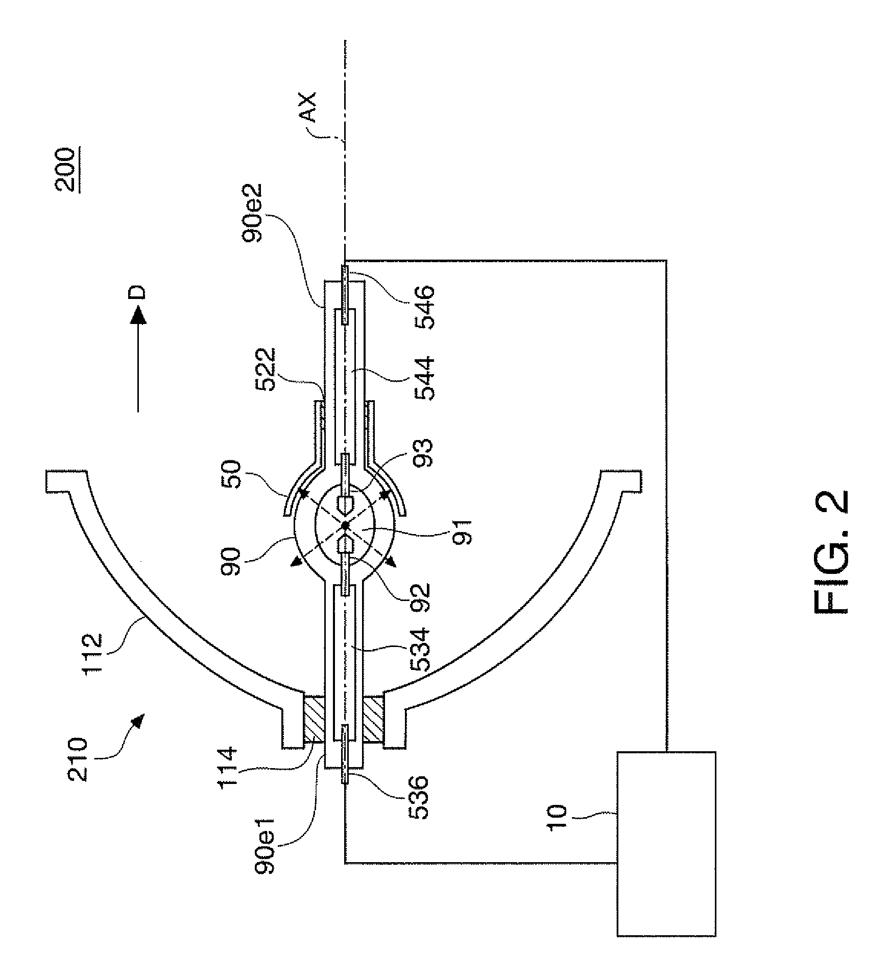
[0039]The light source device 200 has a light source unit 210 and a discharge lamp lighting device 10. The light source unit 210 has a main reflection mirror 112, a sub-reflection mirror 50 (which will be descri...


PUM


Abstract

A projector that outputs a first image and a second image alternately while performing switching between the first image and the second image, includes: a discharge lamp driving section that supplies, to a discharge lamp, a drive current that drives the discharge lamp; a state detecting section that detects a deteriorating state of the discharge lamp; and a control section that controls the discharge lamp driving section, wherein the control section controls the discharge lamp driving section so that the absolute value of the drive current becomes relatively small in a first period and relatively large in a second period and controls the discharge lamp driving section so that the ratio of the absolute value of the drive current in the second period to the absolute value of the drive current in the first period is increased with the progress of the deteriorating state.

Description

BACKGROUND[0001]1. Technical Field[0002]The present invention relates to projectors.[0003]2. Related Art[0004]A projector using a discharge lamp such as a high-pressure mercury lamp or a metal halide lamp has been put to practical use. As such a projector, in JP-A-2003-102030, for example, a projector having a unit for varying the intensity of a light source in accordance with a color separation unit or the like in synchronization with a image signal is disclosed. However, JP-A-2009-237302 describes that if the intensity of the light source is simply varied, an electrode of the discharge lamp will wear out significantly.[0005]Moreover, in recent years, a projector that outputs a stereoscopic image by using a discharge lamp such as a high-pressure mercury lamp or a metal halide lamp has been put to practical use.[0006]One of the methods to output a stereoscopic image is a method by which switching between a image for the right eye and a image for the left eye is performed and the ima...

Claims


Application Information

Patent Timeline
Patent Type & Authority Patents(United States)
IPC IPC(8): H05B41/16
CPCH05B41/2928G03B21/2026G03B35/16H04N9/3155Y02B20/208Y02B20/00
Inventor TERASHIMA, TETSUOSATO, SHUN
Owner SEIKO EPSON CORP
Why Eureka
Try Eureka