Sheet hole punching device

a hole punching and sheet technology, applied in the field of sheet hole punching devices, can solve problems such as punching holes in sheets

Inactive Publication Date: 2014-07-08
SEIKO CORP
View PDF15 Cites 3 Cited by
  • Summary
  • Abstract
  • Description
  • Claims
  • Application Information

AI Technical Summary

Benefits of technology

[0013]The present invention provides a hole-punching method and hole-punching device that can store large volumes of paper cutting debris without the paper cutting debris entering the device, and without increased loads on the hole-punching blades, when punching holes in sheets such as with punch members.
[0014]The present invention further provides a hole-punching device that can punch holes at high speed without reduced shear load when punching holes and at the same time can be configured with a compact and lightweight drive mechanism.
[0017]Further, the above mentioned second problem accomplishes reduction of punching load by moving the punching members (punching action) in the punching direction as rotating the punching members. The hole punching blades are then structured in inclination so that punching holes in the sheets continuous back and forth is reciprocally reversed. The life of the hole punching blades may be thereby lengthened.
[0019]Further, the present invention is characterized by causing each of the punching members to execute hole punching, not integrally connected, but separated from the punching members the receiving gears of transmitting rotation thereto from the driving rotation shaft and cam members of displacing them in the hole punching direction.

Problems solved by technology

The above mentioned first problem is to punch holes in the sheets by moving the punching members in the punching direction as rotating them by reciprocal rotation of the drive motor.

Method used


Image

  • Sheet hole punching device
  • Sheet hole punching device
  • Sheet hole punching device

Examples


Embodiment Construction

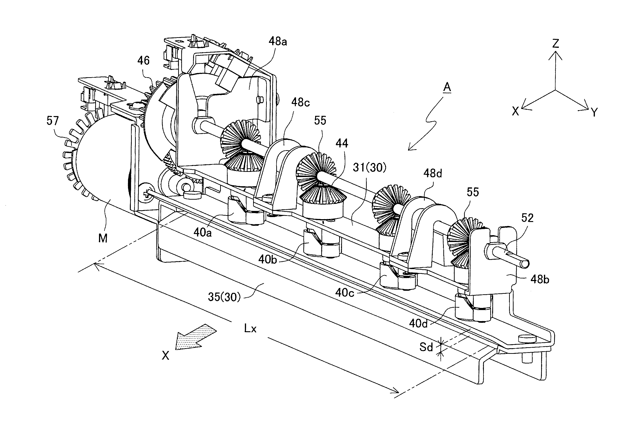
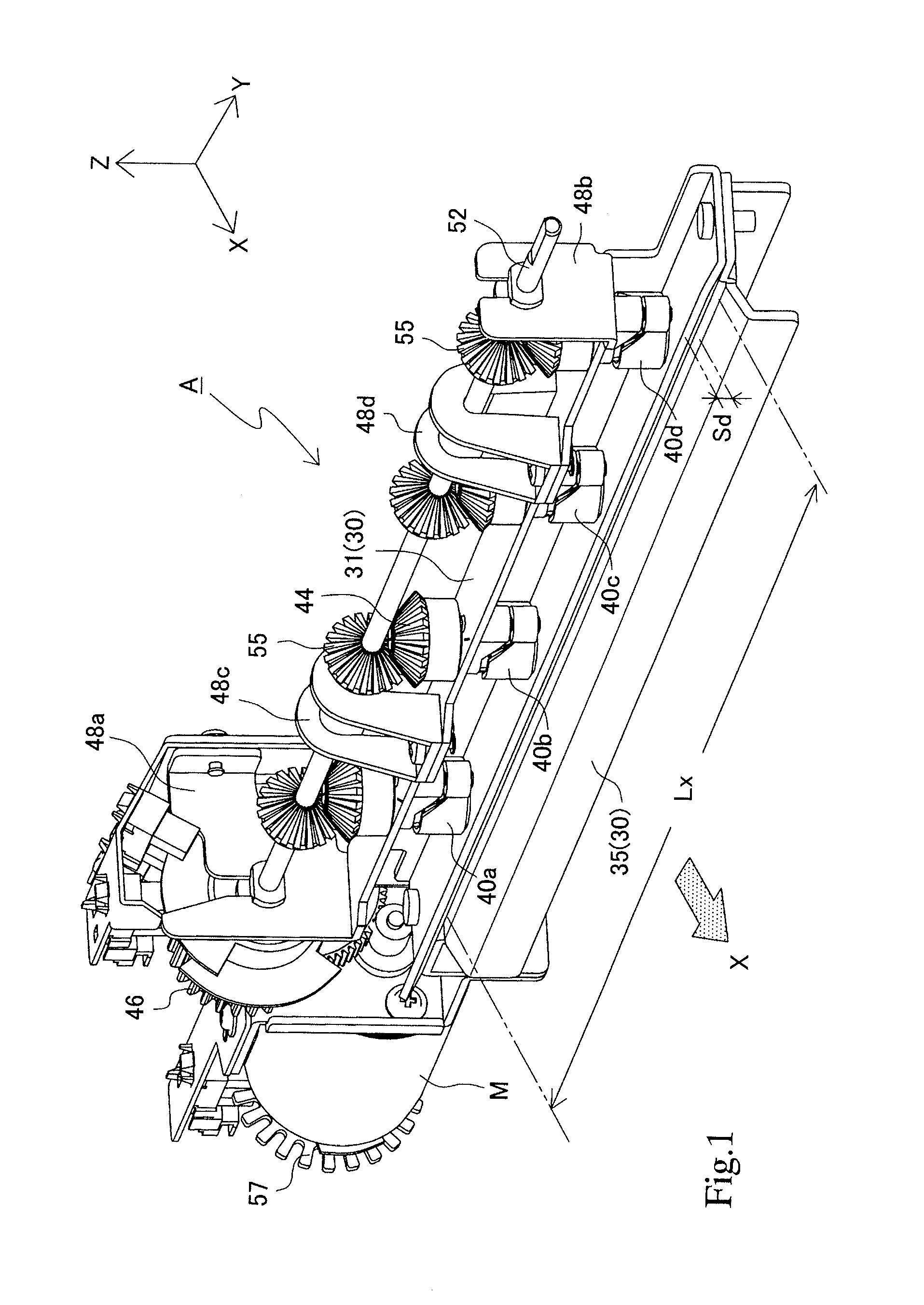
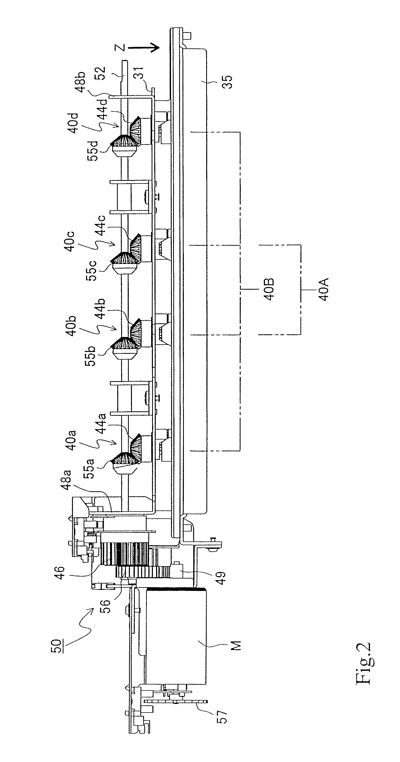
[0034]The present invention will be referred to in detail based on shown preferred embodiments. FIG. 1 is the perspective view showing the whole structure of the hole punching device of paper sheets and the like relating to the present invention, and FIG. 2 is its front view.

[0035]The sheet hole punching device A shown in FIG. 1 is structured for punching 2 or 4 holes otherwise 2 or 3 holes selectively in the sheets. This sheet hole punching device A is composed of a device frame 30, punching members 40 and a drive means 50.

[0036]The device frame 30 is placed in a direction (Y direction) crossing with a sheet sending direction (X direction) and supports a plurality of the punching members 40 in the hole punching direction (Z direction) in a manner that the punching members can move in up and down directions. The punching members 40 are divided in a first group of punching members 40b, 40c (in the following, called generically as 40A) and a second group of punching members 40a, 40b, ...


PUM

PropertyMeasurementUnit
angleaaaaaaaaaa
rotationaaaaaaaaaa
rotational movementaaaaaaaaaa

Abstract

A sheet hole punching device has a device frame; a plurality of punching members arranged in first and second groups, and arranged linearly on the device frame; a driving rotation shaft; a driving motor reciprocally rotating the driving rotation shaft; a gear mechanism transmitting a rotation of the driving rotation shaft; cam mechanisms converting the rotational movement; and a motor control device. The gearing mechanism includes drive gears disposed on the drive rotational shaft, and receiving gears disposed on the punching members to engage with the drive gears. The cam mechanisms include cam followers and cylindrical cams. The cylindrical cam has a V-shaped groove cam to reciprocate each of the punching members between an upper dead point and a lower dead point. The punching members are rotated in one direction to punch holes in first sheets, and subsequently rotated in a reverse direction to punch holes in following sheets.

Description

CROSS-REFERENCE TO RELATED APPLICATIONS[0001]The present application is a continuation-in-part application of Ser. No. 12 / 923,464, filed on Sep. 23, 2010, which is a divisional application of Ser. No. 11 / 727,940, now U.S. Pat. No. 7,823,494.BACKGROUND OF THE INVENTION[0002]1. Field of the Invention[0003]The present invention relates to a h hole punching device used in conjunction with image forming apparatus, that punch holes in sheets conveyed out from an image forming apparatus such as a copier, printing machine or printer and the like.[0004]2. Description of Related Arts[0005]Generally, hole-punching devices that punch holes in sheets by manually pushing hole-punching members downward into a plurality of sheets, and automatic hole-punching devices that punch holes in sheets conveyed out of a printing machine or copier are well known as office devices for punching holes in sheets, such as paper, for filing. The former is widely known as a device for penetrating sheets by disposing...

Claims


Application Information

Patent Timeline
Patent Type & Authority Patents(United States)
IPC IPC(8): B26F1/04
CPCB26D7/1818G03G15/6582B26F1/04G03G2215/00818Y10T408/858B26F1/14Y10T83/943Y10T83/8843B26D5/16B26F1/16Y10T83/8828
Inventor BABA, KENJIHASEBE, YUJIHOSHINO, YOSHINORI
Owner SEIKO CORP
Why Eureka
Try Eureka