Dampers for mountain bikes

a technology for mountain bikes and hammers, applied in the direction of shock absorbers, cycle equipment, cycles, etc., can solve the problems of poor handling, suspension of ‘packing down, and period of zero wheel contact for

Inactive Publication Date: 2014-07-08
UNIV OF SHEFFIELD
View PDF21 Cites 72 Cited by
  • Summary
  • Abstract
  • Description
  • Claims
  • Application Information

AI Technical Summary

Benefits of technology

[0032]It is preferable that said threshold value and specific time period be such that when incorporated into the present invention, the damper is controlled so as to provide high damping (hard suspension) when the rider is riding on smooth ground, and low damping (soft suspension) when the rider is riding on rough ground.
[0054]It is preferable that the first, second or third aspect of the present invention provides an integrated stand alone unit that can be retrofitted to existing bicycles. With regards to the first and third aspects of the present invention, it is preferable that said sensor and controller are integrated on the housing providing a compact arrangement that is minimally disruptive to other systems of the bicycle.

Problems solved by technology

A rebound damping rate that is too high in this situation would cause the suspension to ‘pack down’ over subsequent bumps because it has insufficient time to rebound before the next obstacle.
This can lead to poor handling as the wheel may skip between bumps resulting in periods of zero wheel contact force.
Furthermore, passenger discomfort is degraded due to the more compressed state of the spring, which transmits larger forces to the rider.
However, when a bike fitted with a suspension system is ridden on a smooth terrain, for example on a road, the suspension system will dissipate some energy input by the rider pedalling.
The energy used in this way does not contribute to the forward propulsion of the bicycle and so reduces the efficiency of each rotation of the pedals.
Therefore, the benefits gained from using a conventional suspension system on rough terrain come at the expense of reduced rider efficiency when travelling on smooth terrain.
Due to the threshold requirement of the U.S. Pat. No. 6,978,872 damper, bump absorption is compromised when travelling over rougher terrain.
This device is based upon the principle of controllable orifice damping which serves to increase high velocity damping and is less effective at low velocities.

Method used


Image

  • Dampers for mountain bikes
  • Dampers for mountain bikes
  • Dampers for mountain bikes

Examples


Embodiment Construction

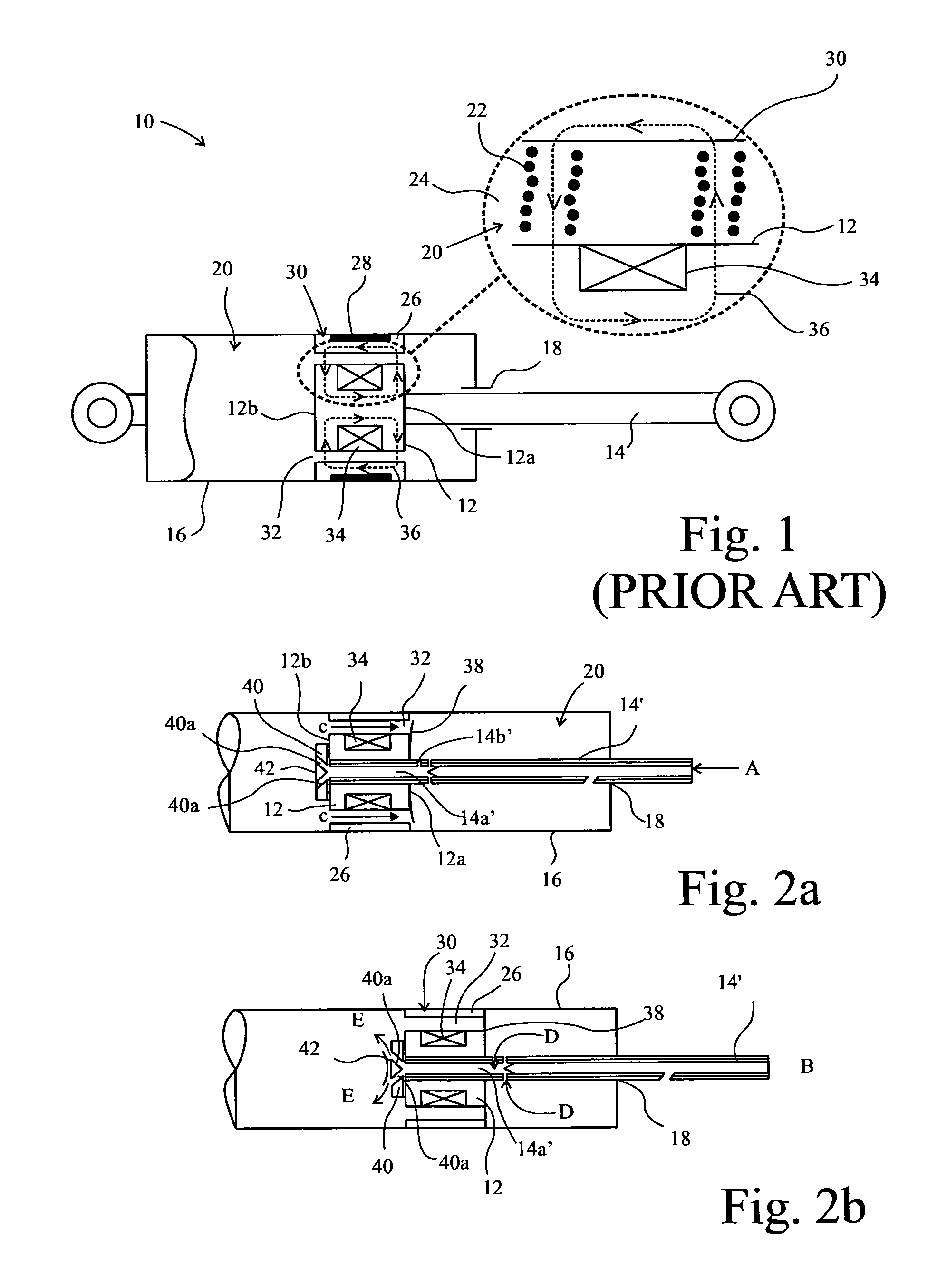
[0065]FIG. 1 shows a typical magnetorheological (MR) damper 10 forming part of the prior art. The damper 10 comprises a bobbin 12 attached at one end of a shaft 14. The bobbin 12 is disposed within a chamber 16 containing MR fluid 20. The MR fluid consists of a suspension of micron-sized ferromagnetic particles 22 (see FIG. 1 insert) distributed in a carrier liquid 24.

[0066]The shaft 14 extends from within the chamber 16 through an opening 18 that comprises a seal. The seal ensures that the chamber 16 remains fluid tight whilst allowing the shaft 14 and bobbin 12 to slidably move along a direction parallel the length of the shaft 14. The bobbin has a proximal end 12a proximal the opening 18 and a distal end 12b, distal the opening 18.

[0067]The bobbin 12 is connected to and circumscribed by a bobbin ring 30 such that the bobbin ring 30 moves collectively with the bobbin within the chamber 12. The bobbin ring 30 is attached to the bobbin 12 by connectors (not shown) and spaced apart f...


PUM


Abstract

An apparatus of a damper (46) for a bicycle comprising a housing defining a chamber, and a piston, movable in the chamber along a first direction. The apparatus further comprises a controllable means to vary the resistance to movement of the piston in the chamber, a sensor (62), and a controller (58) including a timer. Said sensor measures at least one dynamic quantity and produces an output signal based thereon. Said output signal is received by the controller, and said controller controls said controllable means based on said dynamic quantity as a function of time to control the level of damping. The invention further provides means for manually adjusting the level of rebound damping.

Description

[0001]This invention relates to dampers and in particular to an improved damper system for use with bicycle shock absorbers.BACKGROUND[0002]Mountain biking is a popular recreational and competitive sport that involves riders travelling over various terrain. To improve rider comfort, most modern mountain bikes are now equipped with suspension systems that aim to absorb bumps and vibrations and improve handling performance. Such suspension systems include energy storage and dissipation elements integrated onto the bicycle frame, which minimise the transmission of vertical perturbations to the rider. Examples include coil or gas springs for energy storage and liquid or gas based dampers for energy dissipation.[0003]The suspension system components above the shock absorber (front triangle, rider mass etc) are often referred to as the sprung mass, whilst the components below the shock absorber are often referred to as the unsprung mass (wheel, tyre etc). Movement of the sprung mass towar...

Claims


Application Information

Patent Timeline
Patent Type & Authority Patents(United States)
IPC IPC(8): F16F9/53
CPCF16F9/53B60G17/018B60G17/08B60G2202/24B60G2300/12B60G2400/204B60G2600/02B60G2600/1882B62K25/04B62K25/28B62K2025/044B62K2025/048B60G17/06B62K25/286F16F9/504F16F9/5126F16F9/535
Inventor SIMS, NEIL DAVIDBATTERBEE, DAVID CRAIG
Owner UNIV OF SHEFFIELD
Why Eureka
Try Eureka