Deployable footrest assembly

a footrest and assembly technology, applied in the direction of chairs, pedestrian/occupant safety arrangements, vehicular safety arrangements, etc., can solve the problem that the fixed footrest assembly can become impractical

Inactive Publication Date: 2014-07-08
FORD GLOBAL TECH LLC
View PDF13 Cites 25 Cited by
  • Summary
  • Abstract
  • Description
  • Claims
  • Application Information

AI Technical Summary

Benefits of technology

[0004]The present invention includes a deployable footrest assembly, wherein a footrest is actuated by way of an actuator which is attached to a top plate that rotates to a deployed position. During deployment, the top plate is released from a housing by moving a latch mechanism to an unlatched position. Once the top plate is released from the housing, the actuator provides an in-line spring assist feature to linkage arms of a linkage assembly. During deployment, the linkage arms rotate to a fixed or set position thereby allowing a vehicle occupant to use the unit as a deployed footrest. During stowage, the latch assembly is coupled to a stowage mechanism, such that when the latch assembly is actuated, a cable pulls the linkage arms beyond a set locking threshold angle thereby enabling the unit to collapse back to a stowed position.

Problems solved by technology

Further, a fixed footrest assembly can become impractical when considering the driver's side architecture of a park brake pedal and its execution path.

Method used


Image

  • Deployable footrest assembly
  • Deployable footrest assembly
  • Deployable footrest assembly

Examples


Embodiment Construction

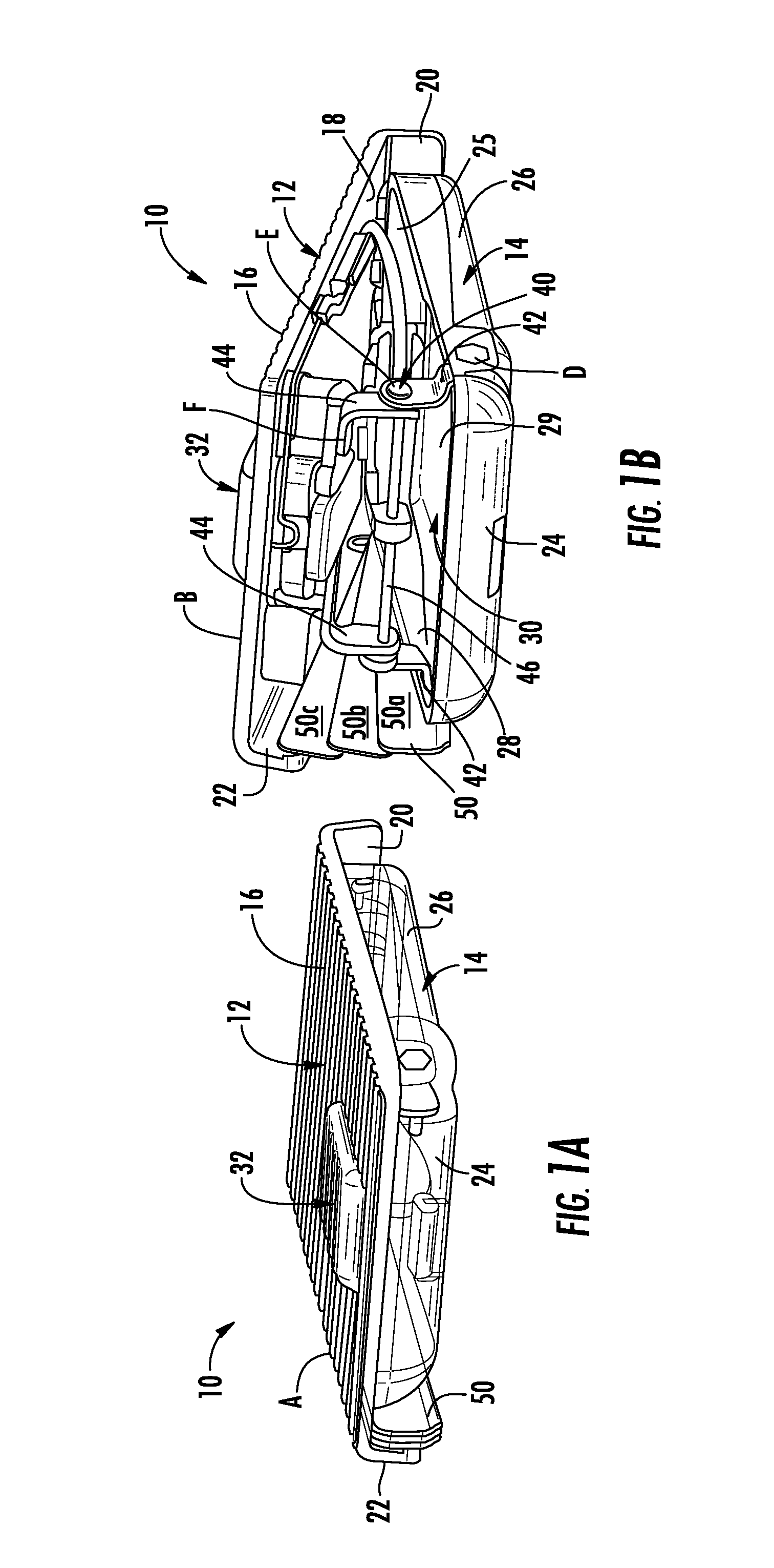
[0031]For purposes of description herein, the terms “upper,”“lower,”“right,”“left,”“rear,”“front,”“vertical,”“horizontal,” and derivatives thereof shall relate to the invention as oriented in FIG. 1. However, it is to be understood that the invention may assume various alternative orientations, except where expressly specified to the contrary. It is also to be understood that the specific devices and processes illustrated in the attached drawings, and described in the following specification are simply exemplary embodiments of the inventive concepts defined in the appended claims. Hence, specific dimensions and other physical characteristics relating to the embodiments disclosed herein are not to be considered as limiting, unless the claims expressly state otherwise.

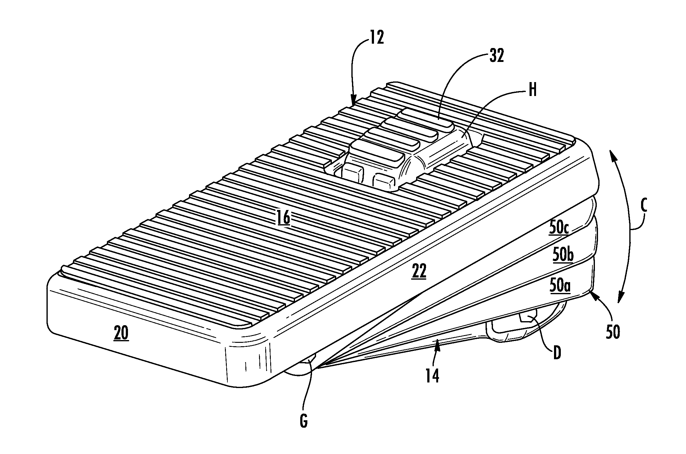
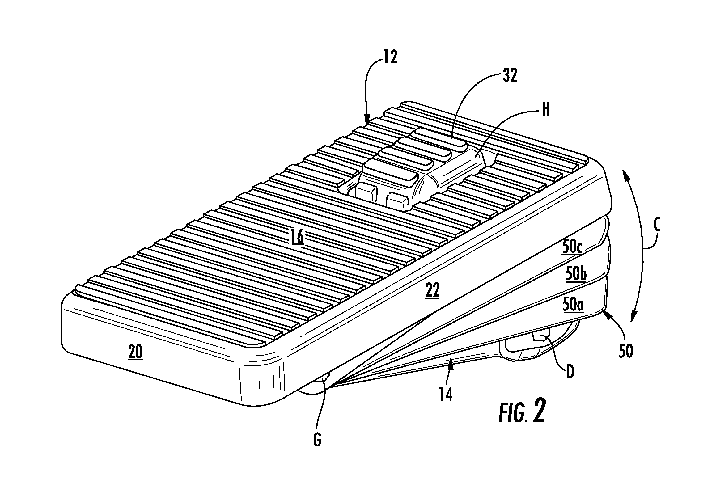
[0032]Referring to FIGS. 1A and 1B, the reference numeral 10 generally designates a deployable footrest assembly which is adapted to be positioned in a vehicle interior in a vehicle occupant compartment on a floorboard. ...


PUM


Abstract

A deployable footrest assembly includes a top plate that is actuated by an actuator such that the top plate is operable between stowed and deployed positions. During deployment, the top plate is released from a housing by moving a latch mechanism to an unlatched position. Once the top plate is released from the housing, the actuator provides an in-line assist feature to linkage arms of a linkage assembly. Powered by the actuator, the linkage arms rotate to a fixed or set position thereby allowing a vehicle occupant to use the unit as a deployed footrest. During stowage, the latch assembly is coupled to a stowage mechanism, such that when the latch assembly is actuated, the stowage mechanism pulls the linkage arms beyond the set locking threshold angle thereby enabling the top plate to collapse back to a stowed position.

Description

FIELD OF THE INVENTION[0001]The present invention generally relates to a deployable footrest assembly that is used in an occupant compartment of a vehicle interior, and more particularly, to a deployable footrest assembly having a top plate which is pivotally coupled to a housing between deployed and stowed positions, wherein the top plate is supported by a linkage assembly in the deployed position to thereby provide a vehicle occupant with a footrest assembly on demand. Further, the linkage system of the present invention provides adequate support for a robust footrest assembly that is adapted to collapse under a force realized on the top plate, or other occupant related trigger, as imparted by the vehicle occupant which moves the top plate from the deployed position to the stowed position such that the deployable footrest assembly does not fixedly support the top plate in the deployed position, but can selectively collapse during a collision event as a safety feature.BACKGROUND OF...

Claims


Application Information

Patent Timeline
Patent Type & Authority Patents(United States)
IPC IPC(8): B60R21/16B60N2/90
CPCB60N3/066B60N3/06
Inventor DRAPER, WILLIAM EDWARDMESZAROS, EDWARD JOSEPH LEONARDPORCARI, JOSEPH
Owner FORD GLOBAL TECH LLC
Why Eureka
Try Eureka