Diagnostic imaging apparatus with airflow cooling system

a cooling system and diagnostic imaging technology, applied in the field of cooling system for diagnostic imaging apparatus, can solve the problems of large heat generation of x-ray scanning devices such as x-ray sources and high-voltage generators, large cooling system size and complexity, and the inability to maintain the same level of functionality, and achieve the effect of reducing the number of cooling systems

Active Publication Date: 2014-07-08
MOBIUS IMAGING
View PDF28 Cites 21 Cited by
  • Summary
  • Abstract
  • Description
  • Claims
  • Application Information

AI Technical Summary

Benefits of technology

[0008]In one embodiment, the imaging system further includes a generally C-shaped support gimbal, and the air duct system is at least partially contained within the gimbal. The gimbal supports the gantry, and attaches to the gantry at two opposed ends of the gantry to provide fluid communication between the air duct system and the interior housing of the gantry. In one embodiment, the gimbal is connected to the gantry by a bearing system that includes a through-hole for providing fluid communication between the air duct system and the interior housing of the gantry. The bearing system enables the gantry to tilt with respect to the gimbal upon which it is supported.
[0010]In one embodiment, the gantry includes an airflow bifurcation system that forces airflow entering from a first side of the gantry to be distributed in two directions around the interior of the gantry and to exit through an opening on the opposite side of the gantry. The bifurcation system can include a plurality of bulkheads along the top and bottom paths of the gantry that direct the air along the top and the bottom of the gantry and prevent airflow in the opposing direction. In one embodiment, a plurality of fans are cooperatively associated with the bulkheads to facilitate the airflow in the desired direction.

Problems solved by technology

A number of components of the x-ray scanning device, such as the x-ray source and high-voltage generator, are known to generate a large amount of heat during operation of the system.
These cooling systems can be relatively large and complex, which is not a problem with conventional systems, which are very large and fixed in place.
However, making an x-ray CT scanner mobile, while maintaining the same level of functionality as conventional fixed systems, requires substantial changes to overall system architecture.
The conventional techniques for cooling are not well adapted to small and / or mobile imaging devices.

Method used


Image

  • Diagnostic imaging apparatus with airflow cooling system
  • Diagnostic imaging apparatus with airflow cooling system
  • Diagnostic imaging apparatus with airflow cooling system

Examples


Embodiment Construction

[0023]This application claims the benefit of U.S. Provisional Application No. 61 / 315,462, filed Mar. 19, 2010, and is related to U.S. application Ser. No. 12 / 576,681, filed Oct. 9, 2009, and to U.S. Provisional Application No. 61 / 313,299, filed Mar. 12, 2010. The entire disclosures of the above-referenced applications are incorporated herein by reference.

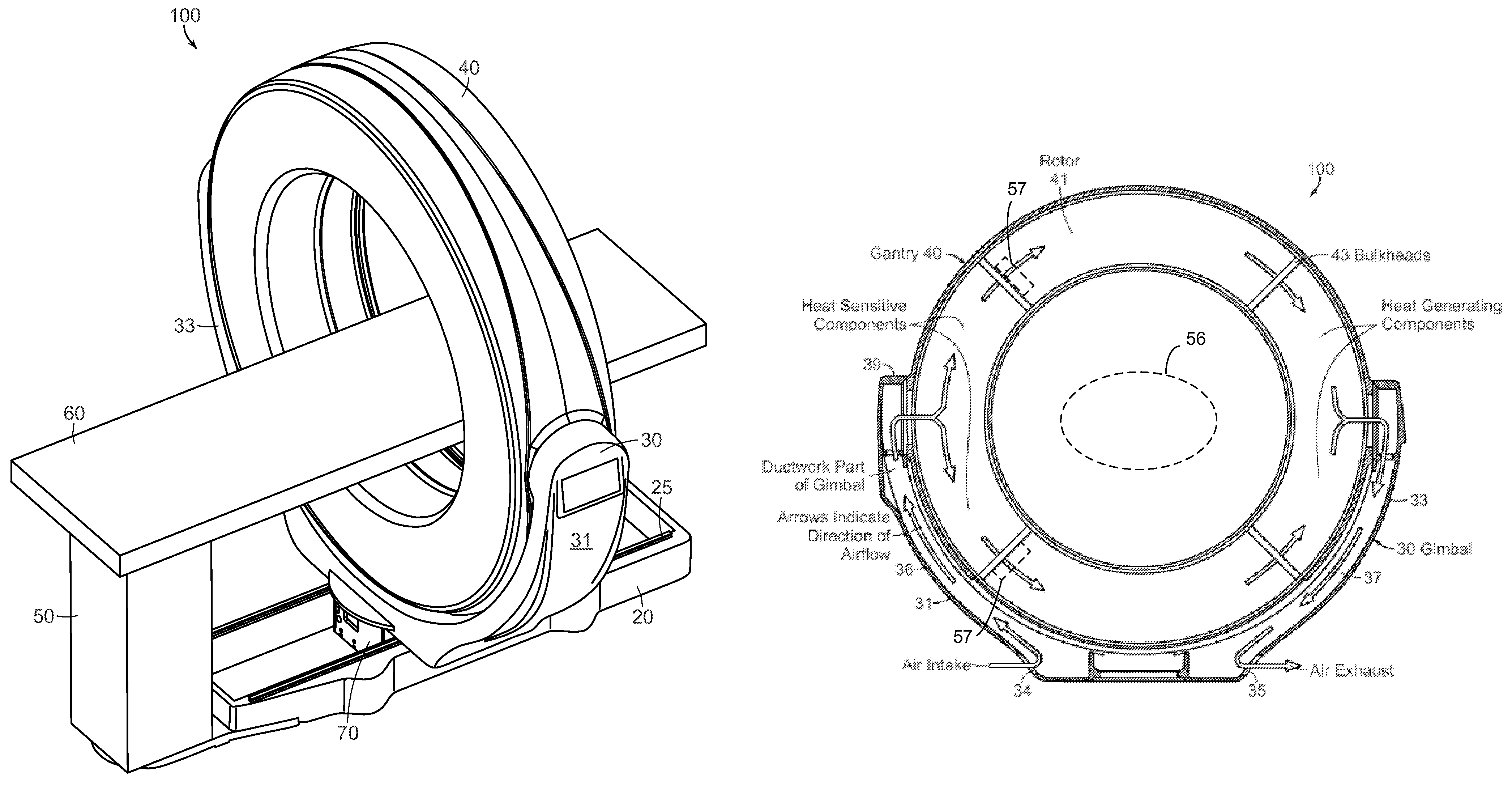
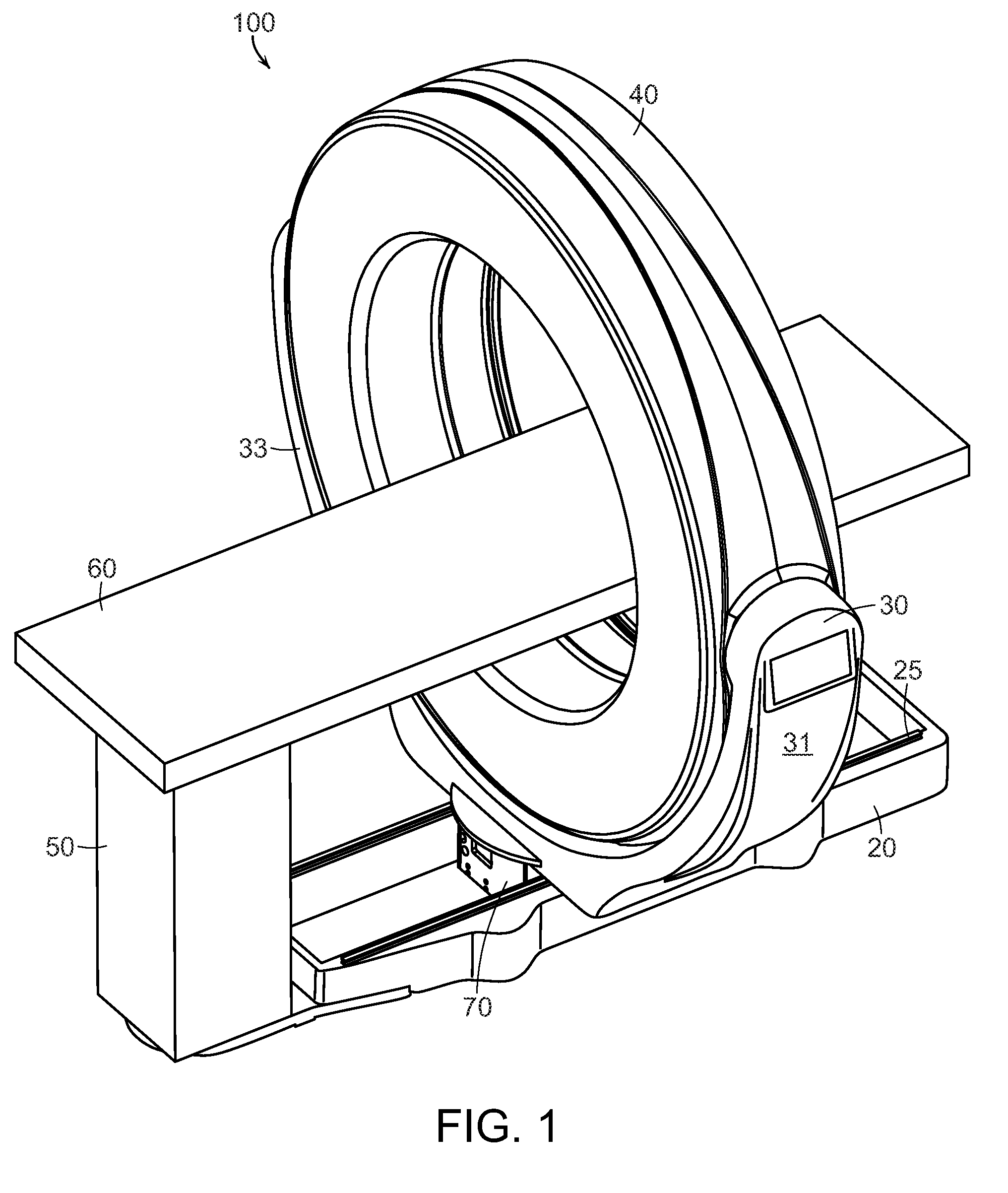
[0024]Referring to FIG. 1, a mobile imaging system 100 according to one embodiment of the invention includes a mobile base 20, a gimbal 30, a gantry 40, and a pedestal 50. The system 100 includes image collection components, such as a rotatable x-ray source and detector array or stationary magnetic resonance imaging components, that are housed within the gantry 40. The system 100 is configured to collect imaging data, such as, for example x-ray computed tomography (CT) or magnetic resonance imaging (MRI) data, from an object located within the bore of the gantry 40, in any manner known in the medical imaging field. The pedestal 50 i...


PUM


Abstract

A diagnostic imaging system, which can be a mobile or stationary surgical CT imaging system or an MRI system, comprises an internal airflow cooling system that includes an air intake opening and an air outtake opening that are positioned near the ground and direct air flow away from the sterile surgical field.

Description

CROSS-REFERENCE TO RELATED APPLICATION[0001]This application claims the benefit of U.S. Provisional Application No. 61 / 315,462, filed Mar. 19, 2010, the entire contents of which are incorporated herein by reference.STATEMENT REGARDING FEDERALLY SPONSORED RESEARCH OR DEVELOPMENT[0002]N / ABACKGROUND OF THE INVENTION[0003]The present invention relates to a cooling system for a diagnostic imaging apparatus.[0004]A conventional computed tomography (CT) x-ray scanner is a relatively large, stationary device having a fixed bore, and is typically located in a dedicated x-ray room, such as in the radiology department of a hospital. A number of components of the x-ray scanning device, such as the x-ray source and high-voltage generator, are known to generate a large amount of heat during operation of the system. Other components, such as the x-ray detector, are very sensitive to heat. Conventional CT scanners typically include cooling systems to manage heat flow, and ensure that the heat gener...

Claims


Application Information

Patent Timeline
Patent Type & Authority Patents(United States)
IPC IPC(8): H05G1/02H05G1/00
CPCA61B6/4423A61B5/055G06F3/0481A61B6/4429G01R33/3804A61B6/4488A61B6/035A61B6/4405A61B34/25G06F9/451A61B6/44A61N2005/002A61N2005/0632F01P1/00F01P5/02F01P5/06F01P7/02F01P11/10
Inventor GREGERSON, EUGENE A.STANTON, RUSSELLALLEN, MICHAELCONNOR, MICHAELCOPPEN, SCOTT
Owner MOBIUS IMAGING
Why Eureka
Try Eureka