Method and apparatus for fluting a web in the machine direction

a web and machine direction technology, applied in the field of methods and apparatus for fluting a web in the machine direction, can solve the problems of corrugating a web, structural damage in the web, damage to paperboard or other web materials, etc., and achieve the effect of reducing the width of the web

Active Publication Date: 2014-07-08
INT PAPER CO
View PDF155 Cites 20 Cited by
  • Summary
  • Abstract
  • Description
  • Claims
  • Application Information

AI Technical Summary

Benefits of technology

[0014]A method of forming a longitudinally-corrugated web is also disclosed. The method includes the following steps: uniformly introducing into a web of medium material a full-width array of longitudinal flutes of intermediate geometry as the web travels along a web-travel pathway in a machine direction, thereby reducing the width of the web to substantially a final width that corresponds to a take-up ratio for preselected longitudinal corrugations or other three-dimensional structure to be formed in the web at the aforementioned final width, wherein substantially no portion of the web traverses a flute-forming element in a cross-machine direction while introducing the intermediate-geometry flutes therein.

Problems solved by technology

Corrugating a web in this manner can damage the paperboard or other web material because it introduces a substantial amount of oscillatory frictional and tension forces to the web leading into and while traversing the corrugating nip.
The resulting substantial cyclic peaks in web tension typically produce some structural damage in the web as it is corrugated.
In addition to undesirable tension effects, corrugating the web in the cross-machine direction introduces flutes that extend transverse to the fibers of the paperboard, which typically run the length of the web in the machine direction.
Thus, flutes formed in a cross-machine direction must re-orient and introduce undulations into the paper fibers, which can also lead to reduced strength.
This is commonly referred to as ‘longitudinal corrugating’ or ‘linear corrugating.’ One issue with longitudinal corrugating is that as the longitudinally-extending flutes are formed, they necessarily consume web width (i.e. the extent of the web in the lateral, cross-machine direction) in order to convert the initially flat web into one having hills and valleys.
This introduces a special problem because typical linear-corrugating devices such as linear-corrugating rollers cannot simultaneously gather web width and introduce corrugations without damaging and tearing the web.
This cannot be achieved without damaging and tearing the web.
For this reason, to date carrying out linear corrugating is impractical for commercial applications that require conventional flute sizes (e.g. A- through E-flutes) for useful web widths (e.g. final width of 50 inches).
Unfortunately, however, for commercial widths of, e.g. 50 inches or greater, the number of successive sets of opposed rollers that would be needed to successively form the longitudinal flutes is such that the machine would be impractically long, producing a very large footprint.
Accordingly, such a machine is not capable of being retrofitted into existing corrugating lines where space is tight, and for new installations it would take up too much space to be practical.
However, as the paperboard web traverses the labyrinth between the opposing sets of flute-forming bars and is gathered laterally inward, individual paper elements in the web are dragged laterally across the bars thereby introducing position- and time-dependent lateral tension variations and oscillations throughout the web, which are undesirable and may contribute to damage.

Method used


Image

  • Method and apparatus for fluting a web in the machine direction
  • Method and apparatus for fluting a web in the machine direction
  • Method and apparatus for fluting a web in the machine direction

Examples


Embodiment Construction

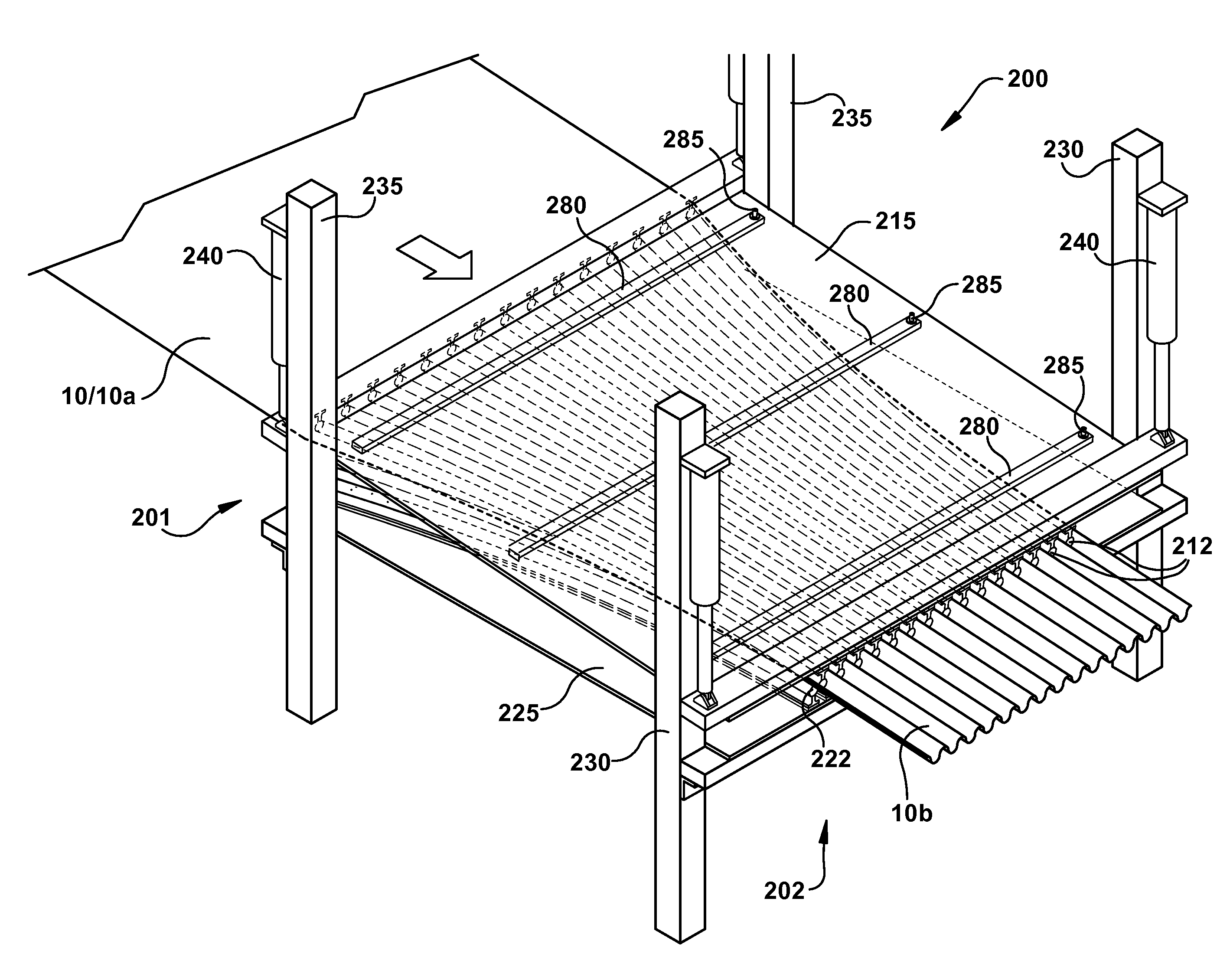
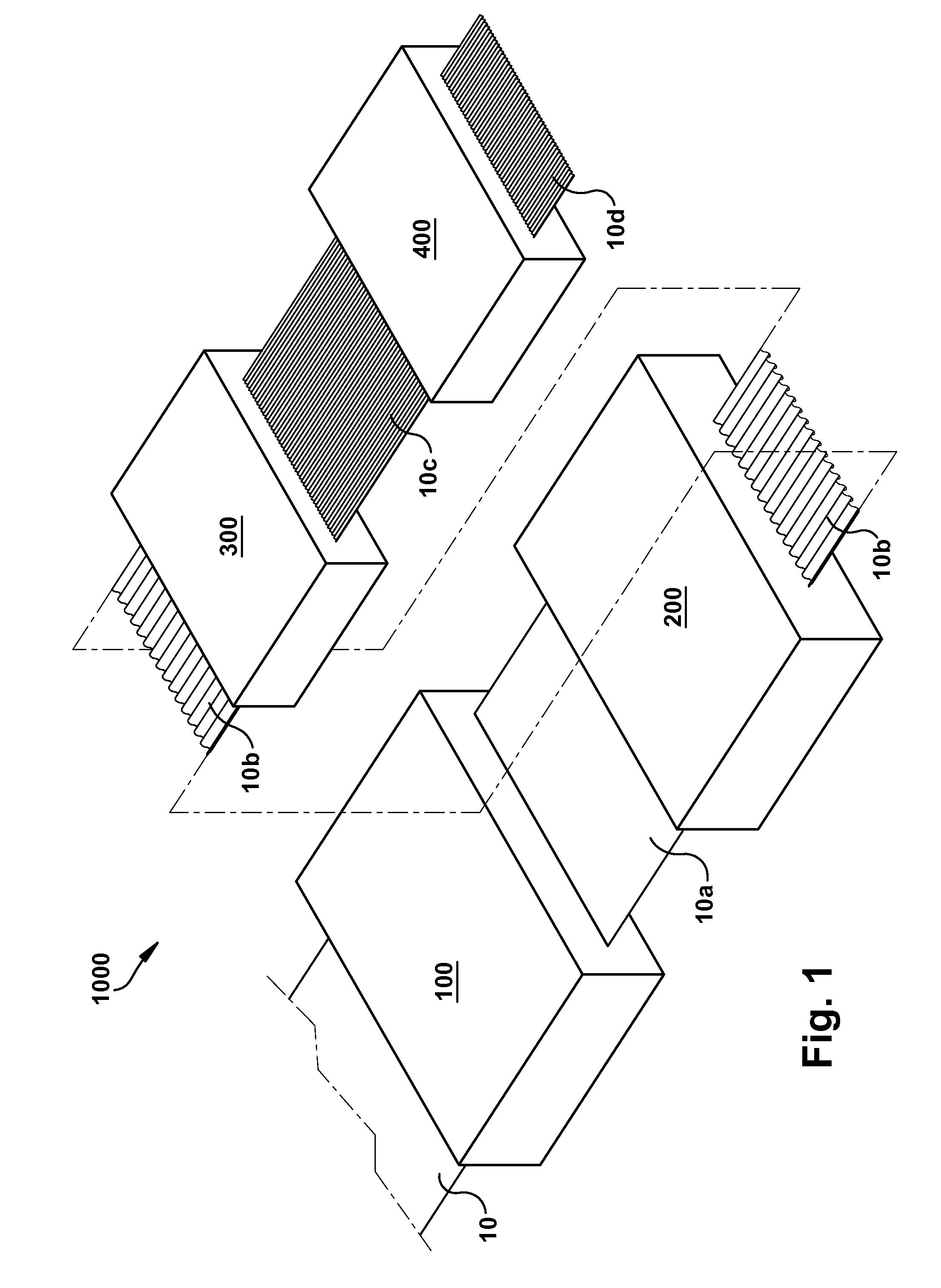
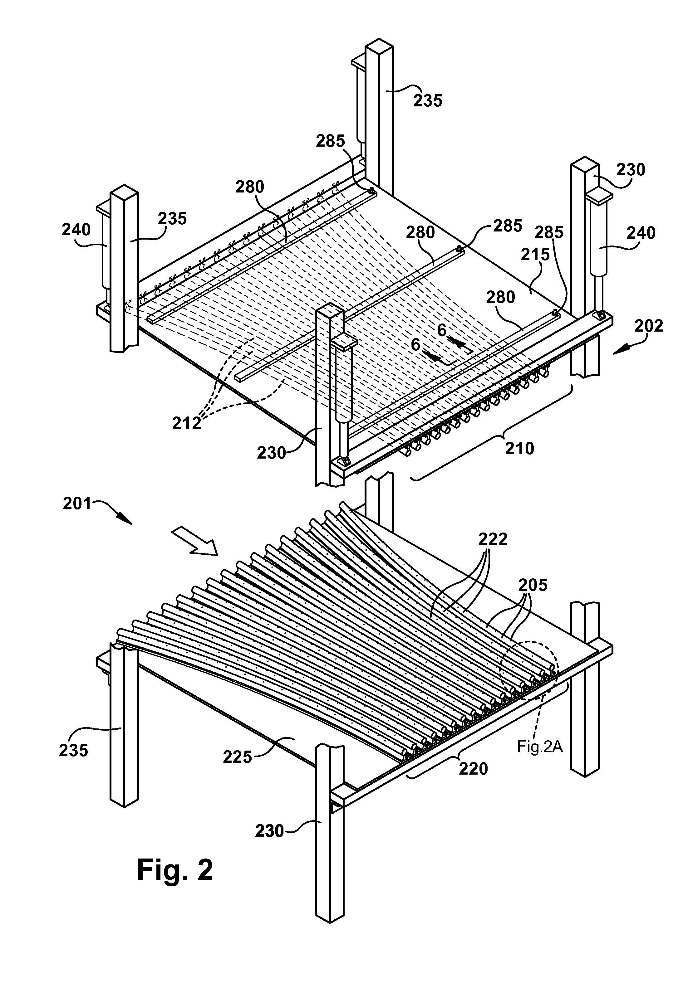
[0034]FIG. 1 schematically illustrates a longitudinal corrugating line 1000. In the illustrated embodiment the corrugating line 1000 includes, in the machine direction along the web-travel pathway of a web 10 of corrugating medium, a preconditioning apparatus 100, a forming device 200, a corrugating die 300 and a final corrugating apparatus 400. In FIG. 1, a single web 10 of corrugating medium is traveling along the web-travel pathway through the corrugating line 1000 in the machine direction. The web is denoted by reference numerals 10, 10a, 10b, 10c and 10d in FIG. 1, corresponding to different stages in the line 1000 wherein the web has been conditioned or treated or manipulated in different operations as more fully described below.

[0035]Briefly, in FIG. 1 the web 10 is initially fed from a source of corrugating medium (e.g. from rolls as is conventional in the art, not shown) to the preconditioning apparatus 100. In the preconditioning apparatus 100, the moisture and / or temperat...


PUM


Abstract

A forming device for gathering the width of a traveling web is disclosed. The forming device includes opposing arrays of flute-forming bars that can be interlaced to define therebetween a longitudinal flute-forming labyrinth effective to reduce the width of a web traveling therethrough by a preselected take-up ratio. The flute-forming bars are curved beginning at an entry end of the forming device such that they converge in a lateral direction as they proceed in the machine direction. In this manner, individual elements of the web traveling between the respective arrays in the machine direction follow contour lines along the curved bars or between adjacent ones of the curved bars so that no such element crosses any flute-forming bar in the cross-machine direction as the web travels and is fluted. A corrugating die for introducing a near-net shape to the intermediate-fluted web is also disclosed, as are a corrugating line incorporating these operations and methods for its operation.

Description

CROSS-REFERENCE TO RELATED APPLICATIONS[0001]This application claims the benefit of U.S. Provisional Patent Application Ser. No. 61 / 721,079 filed Nov. 1, 2012, which is incorporated herein by reference.BACKGROUND[0002]Corrugated webs possess increased strength and dimensional stability compared to un-corrugated (i.e. flat) webs of the same material. For example, corrugated paperboard or cardboard is widely used in storage and shipping boxes and other packaging materials to impart strength. A typical corrugated cardboard structure known as ‘double-wall’ includes a corrugated paperboard web sandwiched between opposing un-corrugated paperboard webs referred to as ‘liners.’ The opposing liners are adhered to opposite surfaces of the corrugated web to produce a composite corrugated structure, typically by gluing each liner to the adjacent flute crests of the corrugated web. This structure is manufactured initially in planar composite boards, which can then be cut, folded, glued or otherw...

Claims


Application Information

Patent Timeline
Patent Type & Authority Patents(United States)
IPC IPC(8): B31F1/22
CPCB29D16/00B31F1/22Y10T156/101Y10T156/1008B31F1/225
Inventor KOHLER, HERBERT, B.
Owner INT PAPER CO
Why Eureka
Try Eureka