One sided thin film capacitive touch sensors

a capacitive touch sensor and thin film technology, applied in the direction of resisting/reacting/inhibiting, pulse technique, instruments, etc., can solve the problems of insufficient use of thin film capacitive touch sensors, lack of three-dimensional character and physical interaction inherent in typical board-based games, and lack of conventional board games with audio and/or visual interaction and computerized game play. , to achieve the effect of simple construction and low cos

Active Publication Date: 2014-07-08
PURE IMAGINATION
View PDF17 Cites 12 Cited by
  • Summary
  • Abstract
  • Description
  • Claims
  • Application Information

AI Technical Summary

Benefits of technology

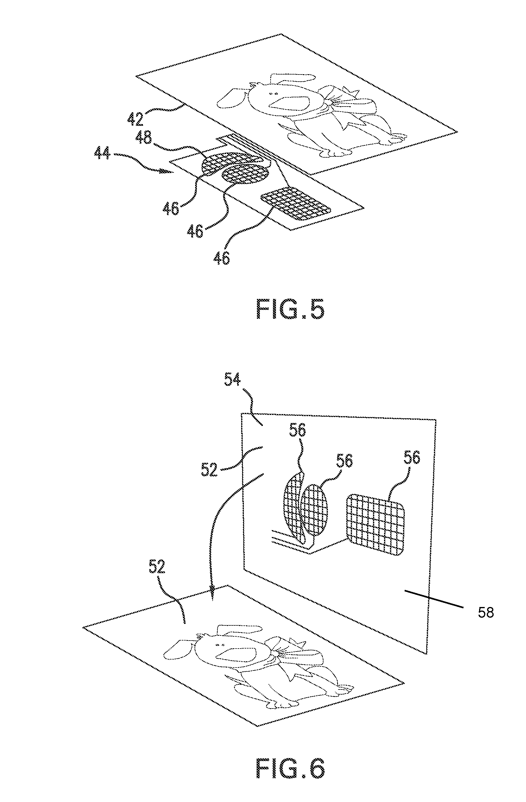
[0019]The system and method for thin capacitive touch sensors of the present invention present numerous advantages, including: (1) inexpensive and simple construction; (2) substantially one-sided triggering of the capacitive touch sensors in particular for hand-held devices; (3) thin construction; (4) touch sensing application to games, board games, toys, books, and greeting cards; and (5) integration of printed art on a layer or substrate with the capacitive touch sensors.

Problems solved by technology

Thin film capacitive touch sensors are known, such as those taught in U.S. Pat. No. 6,819,316 “Flexible capacitive touch sensor.” However, thin film capacitive touch sensors not used as much due to several technical challenges, including a “two-sided” effect that makes thin film capacitive touch sensors sensitive to touch on both sides of the sensor.
Such displays lack the three-dimensional character and physical interaction inherent in typical board-based games.
Conversely, conventional board games often lack the audio and / or visual interaction and computerized game play offered by computer games.
The complexity and cost of such a system make it impractical for low-cost games and toys.
Each system requires a resonator circuit coupled with some particular feature of each unique game piece, which increases the complexity and cost of the system while reducing the flexibility of use.
This system has the disadvantages of requiring specialized electronic circuitry that may limit the number of sensors that can be simultaneously deployed.
Such a system requires numerous expensive light emitters and light detectors, in particular for increasing the spatial sensitivity for detection.

Method used


Image

  • One sided thin film capacitive touch sensors
  • One sided thin film capacitive touch sensors
  • One sided thin film capacitive touch sensors

Examples


Embodiment Construction

[0215]Before beginning a detailed description of the subject invention, mention of the following is in order. When appropriate, like reference materials and characters are used to designate identical, corresponding, or similar components in differing figure drawings. The figure drawings associated with this disclosure typically are not drawn with dimensional accuracy to scale, i.e., such drawings have been drafted with a focus on clarity of viewing and understanding rather than dimensional accuracy.

[0216]In the interest of clarity, not all of the routine features of the implementations described herein are shown and described. It will, of course, be appreciated that in the development of any such actual implementation, numerous implementation-specific decisions must be made in order to achieve the developer's specific goals, such as compliance with application- and business-related constraints, and that these specific goals will vary from one implementation to another and from one d...


PUM


Abstract

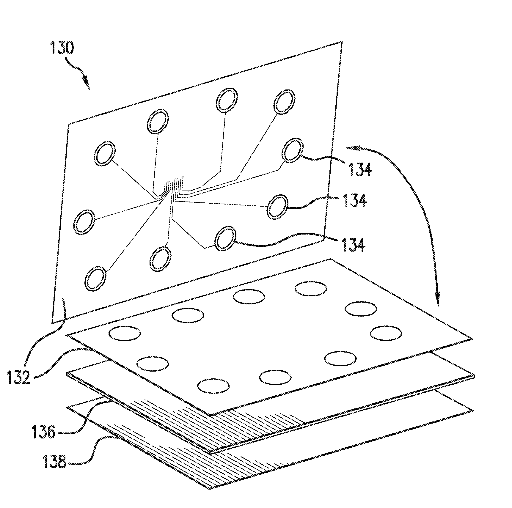
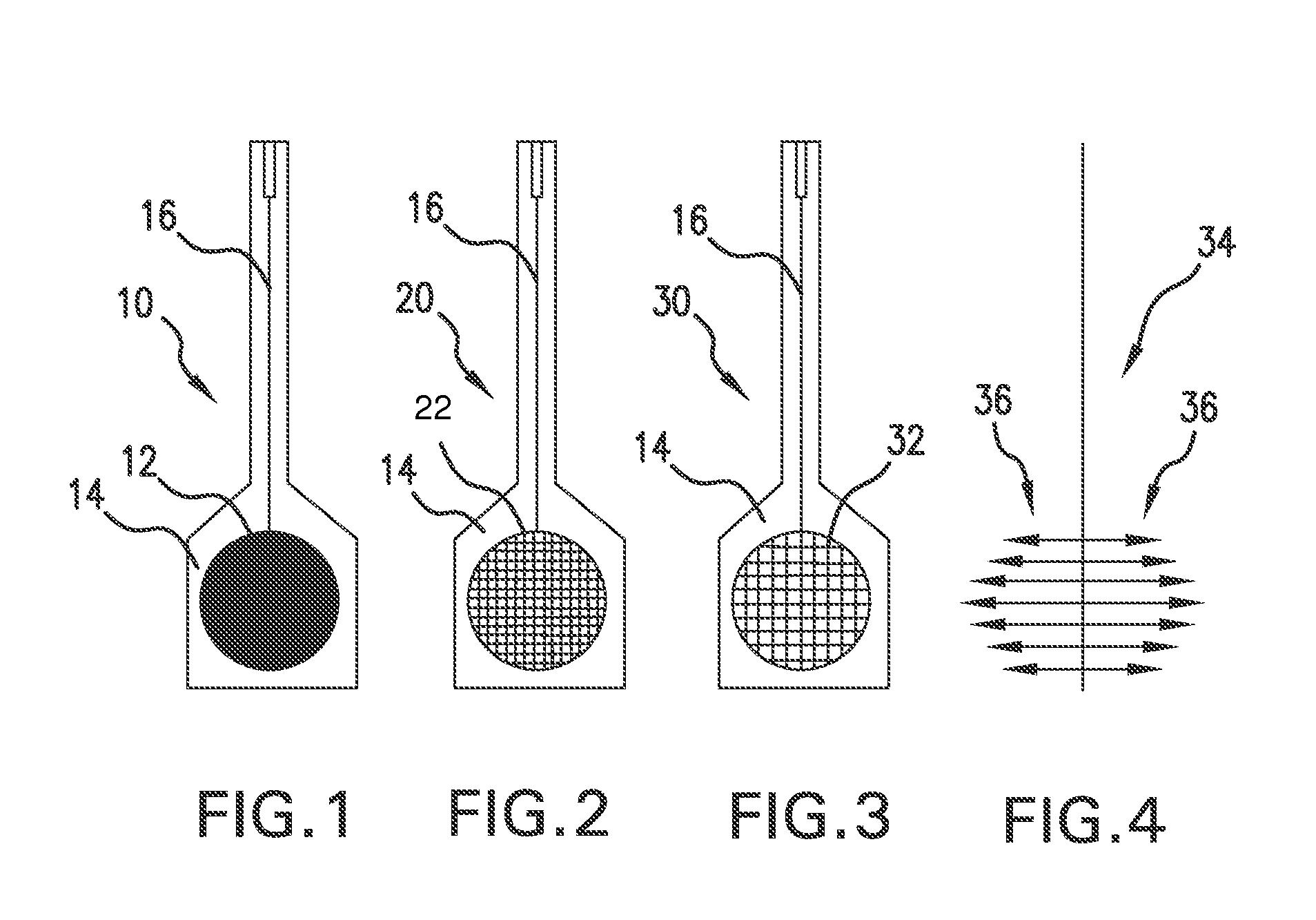
Thin film capacitive touch sensors and applications thereof are described herein. Embodiments include construction of one-sided and two-sided thin film capacitive touch sensors with partial fill patterns, one-sided thin film capacitive touch sensors including conductive ground plane layers, one-sided thin film capacitive touch sensors including air gap layers, one-sided thin film capacitive touch sensors including a combination of both separation layers to create air gap layers and conductive ground plane layers.

Description

CROSS-REFERENCE TO RELATED APPLICATION[0001]This application is a continuation of and claims priority to co-pending Nonprovisional application Ser. No. 13 / 104,878, filed 10 May 2011, which in turn claims priority to U.S. Provisional Application No. 61 / 333,195 filed on May 10, 2010, all of which are incorporated herein by reference.FIELD OF THE INVENTION[0002]The present invention relates to capacitive touch sensors. More particularly, the present invention relates to one-sided thin film capacitive touch sensors.BACKGROUND[0003]Capacitive touch sensors are known and ubiquitous. Their basic operation is relatively simple. A capacitive touch sensor typically is a small capacitor enclosed in an electrical insulator. The capacitor is a device that has an ability to store an electrical charge, referred to as capacitance. When a power source applies an increased voltage across the capacitor, electrical charges flow into the capacitor until the capacitor is charged to the increased voltage....

Claims


Application Information

Patent Timeline
Patent Type & Authority Patents(United States)
IPC IPC(8): G06F3/044
CPCH03K17/975H03K17/962H03K2017/9602H03K2217/96019G01R27/26
Inventor WALLACE, MICHAELODOM, PHILIP T.
Owner PURE IMAGINATION
Why Eureka
Try Eureka