Imaging device, imaging method and recording medium for adjusting imaging conditions of optical systems based on viewpoint images
a technology of viewpoint images and imaging devices, applied in the field of imaging devices, can solve the problems of complex mechanism for changing the convergence angle, inability to obtain appropriate stereoscopic images, and large imaging devices, and achieve good stereoscopic images
- Summary
- Abstract
- Description
- Claims
- Application Information
AI Technical Summary
Benefits of technology
Problems solved by technology
Method used
Image
Examples
first embodiment
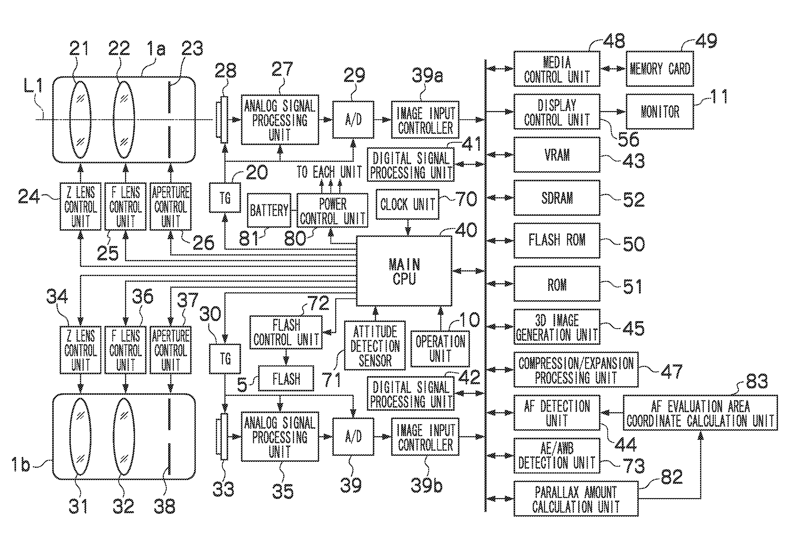
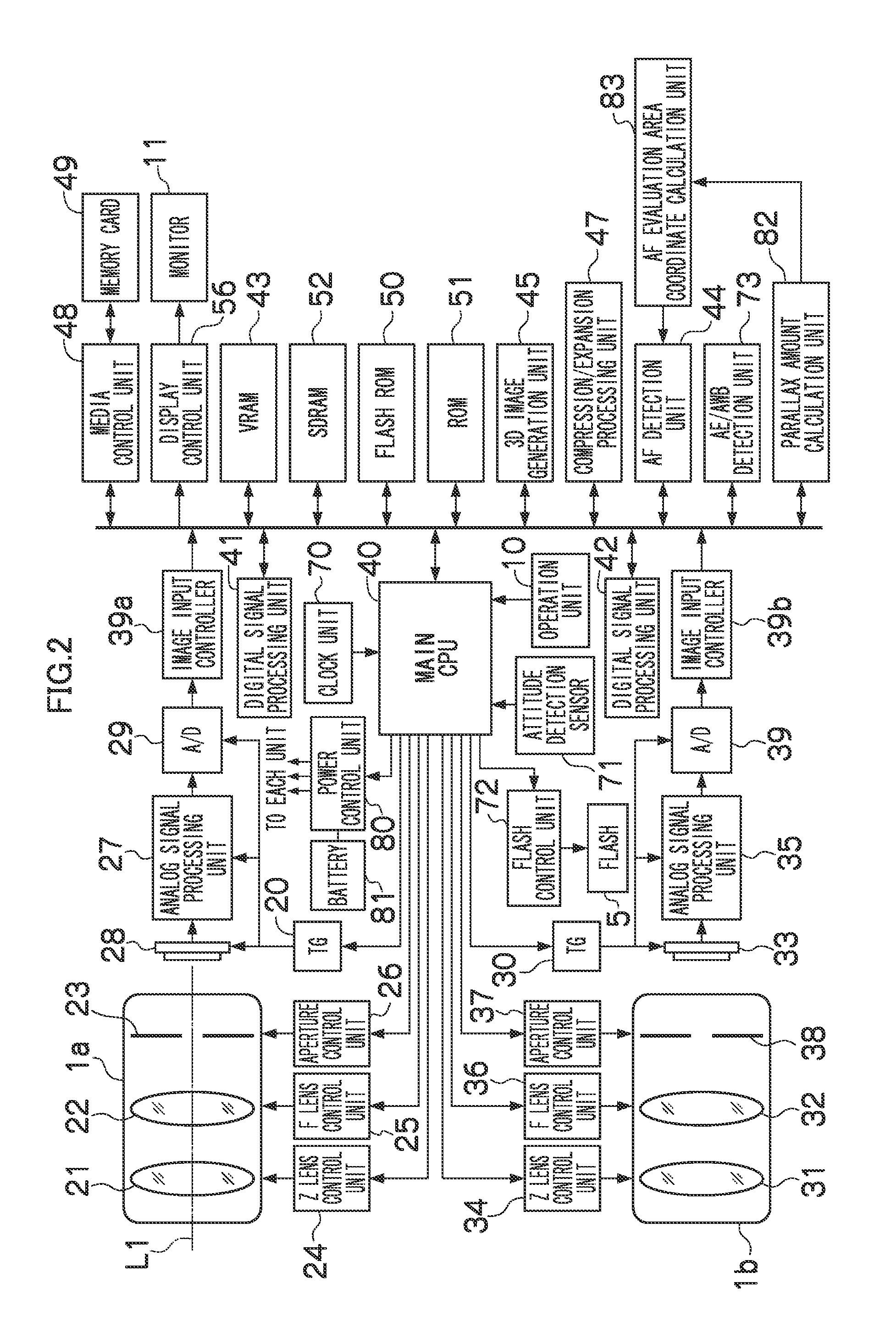
[0097]FIG. 8 illustrates a flowchart of the image taking process according to the presently disclosed subject matter. Execution of this process is controlled by the CPU 40. A program for causing the CPU 40 to execute this process is stored in the ROM 51. It should be noted that a personal computer or the like having a hardware configuration equivalent to the CPU 40 can also control the execution of the following process, and thus, the CPU 40 does not necessarily need to be included in the camera 2.
[0098]In S1, the CPU 40 sets the center coordinates (X, Y) in the AF evaluation area R1-L in the second image data (the image data from the reference imaging unit) which is currently stored in the VRAM 43, and controls the parallax amount calculation unit 82 to detect the feature points in a designated AF evaluation area R1-L and the corresponding points which are the points corresponding thereto in the first image data, and to perform the calculation of the final parallax vector (Δx, Δy) ...
third embodiment
[0100]In S3, the AE / AWB detection unit 73 is controlled to detect the first metered light value, the second metered light value, the first WB (white balance) value and the second WB value from the first and second image data. While the system which calculates the exposure value in the AE / AWB detection unit 73 is arbitrary, the system may be a system of a second or third embodiment to be described later.
[0101]In S4, in response to termination of the detection of the first metered light value, the second metered light value, the first WB value and the second WB value, the following AF process is started. First, the CPU 40 moves the focus lenses 22 and 32 by each predetermined step in a predetermined range (hereinafter referred to as “AF search range”) from a close range to infinity.
[0102]In S5, the center coordinates (X, Y) in the AF evaluation area are set in each second image data obtained by the imaging at each moving position of the reference imaging unit, here, the second image t...
second embodiment
[0115]Hereinafter, with reference to a flowchart of FIG. 11, a flow of the image taking process according to the presently disclosed subject matter will be described. Execution of this process is controlled by the CPU 40. A program for causing the CPU 40 to execute this process is stored in the ROM 51. It should be noted that the personal computer or the like having the hardware configuration equivalent to the CPU 40 can also control the execution of the following process, and thus, the CPU 40 does not necessarily need to be included in the camera 2.
[0116]S21 to 22 are similar to S1 to 2, respectively. In S21, the final parallax vector (Δx, Δy) is defined.
[0117]In S23, in response to the definition of the final parallax vector (Δx, Δy), the following AE process is started.
[0118]In S24, the AE / AWB detection unit 73 is controlled to set a spot metering area R2-L (see FIG. 12A) of a predetermined shape and a predetermined size, which has the center coordinates (X, Y), in the image data...
PUM
 Abstract
Description
Claims
Application Information
 - R&D
- Intellectual Property
- Life Sciences
- Materials
- Tech Scout
- Unparalleled Data Quality
- Higher Quality Content
- 60% Fewer Hallucinations
Browse by: Latest US Patents, China's latest patents, Technical Efficacy Thesaurus, Application Domain, Technology Topic, Popular Technical Reports.
© 2025 PatSnap. All rights reserved.Legal|Privacy policy|Modern Slavery Act Transparency Statement|Sitemap|About US| Contact US: help@patsnap.com


