
Method and device for operating a steam power station comprising a steam turbine and a process steam consumer

a technology of steam power station and process steam, which is applied in the direction of steam engine plants, machines/engines, mechanical equipment, etc., can solve the problems of impermissible pressure and temperature upstream of the low-pressure turbine, the remaining steam, and the high loss, so as to improve the utilization of available steam and improve the efficiency of operation. , the effect of efficient operation

Inactive Publication Date: 2014-07-15
SIEMENS AG
View PDF10 Cites 3 Cited by
  • Summary
  • Abstract
  • Description
  • Claims
  • Application Information

AI Technical Summary

Benefits of technology

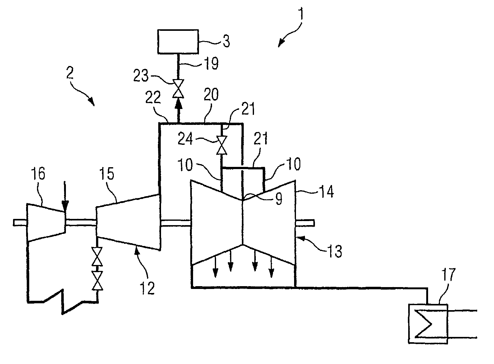
The invention proposes a method for operating a steam power station with a steam turbine and a process steam consumer. The method ensures efficient operation in all operating modes and maximizes the use of available steam. The invention also proposes a steam power station that implements the efficient operation method and maximizes the use of available steam.

Problems solved by technology

However, this has the disadvantage that the throttling of the remaining steam leads, thermodynamically, to high losses.
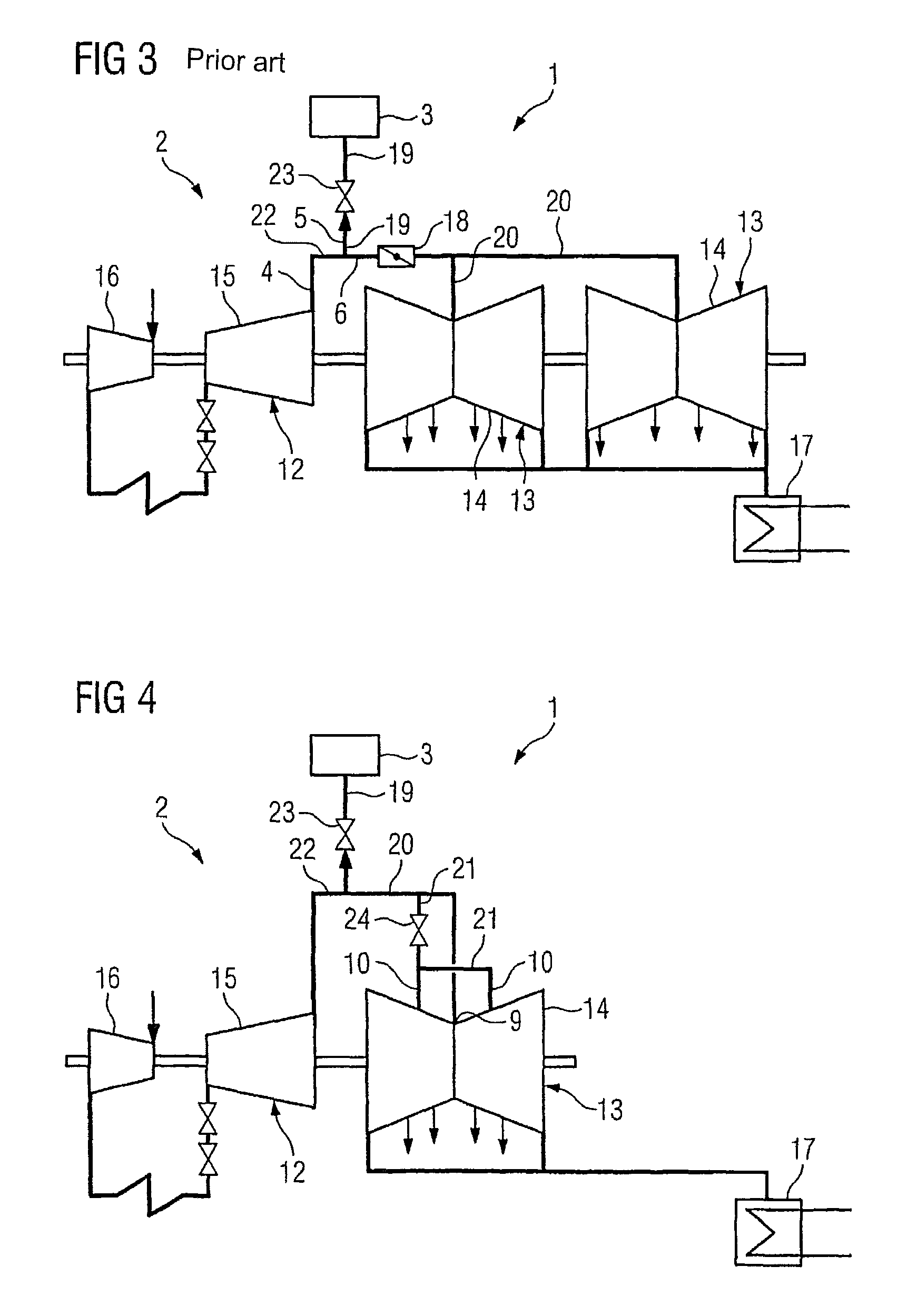
This method has the disadvantage that, if the process steam consumer or the carbon-dioxide separation apparatus fails or is shut down for desired purposes, at least a portion of the excess steam which occurs in this operating state must be dissipated into the condenser since, otherwise, the pressure and the temperature upstream of the low-pressure turbine would rise impermissibly.
Alternatively, the low-pressure turbine and the waste-steam area of the medium-pressure turbine could be designed for higher pressures and temperatures from the start, although this can lead to considerable additional costs.
Steam power stations having process steam consumers as are known from the prior art have the general disadvantage either of losses due to inefficient throttling which is required for operation with a steam output or the loss of excess steam which is created in the operating mode without any steam output, and the steam must be passed to the condenser without being used.
These losses lead to an undesirable deterioration in overall efficiency of the steam power station.

Method used


Image

  • Method and device for operating a steam power station comprising a steam turbine and a process steam consumer
  • Method and device for operating a steam power station comprising a steam turbine and a process steam consumer
  • Method and device for operating a steam power station comprising a steam turbine and a process steam consumer

Examples


Embodiment Construction

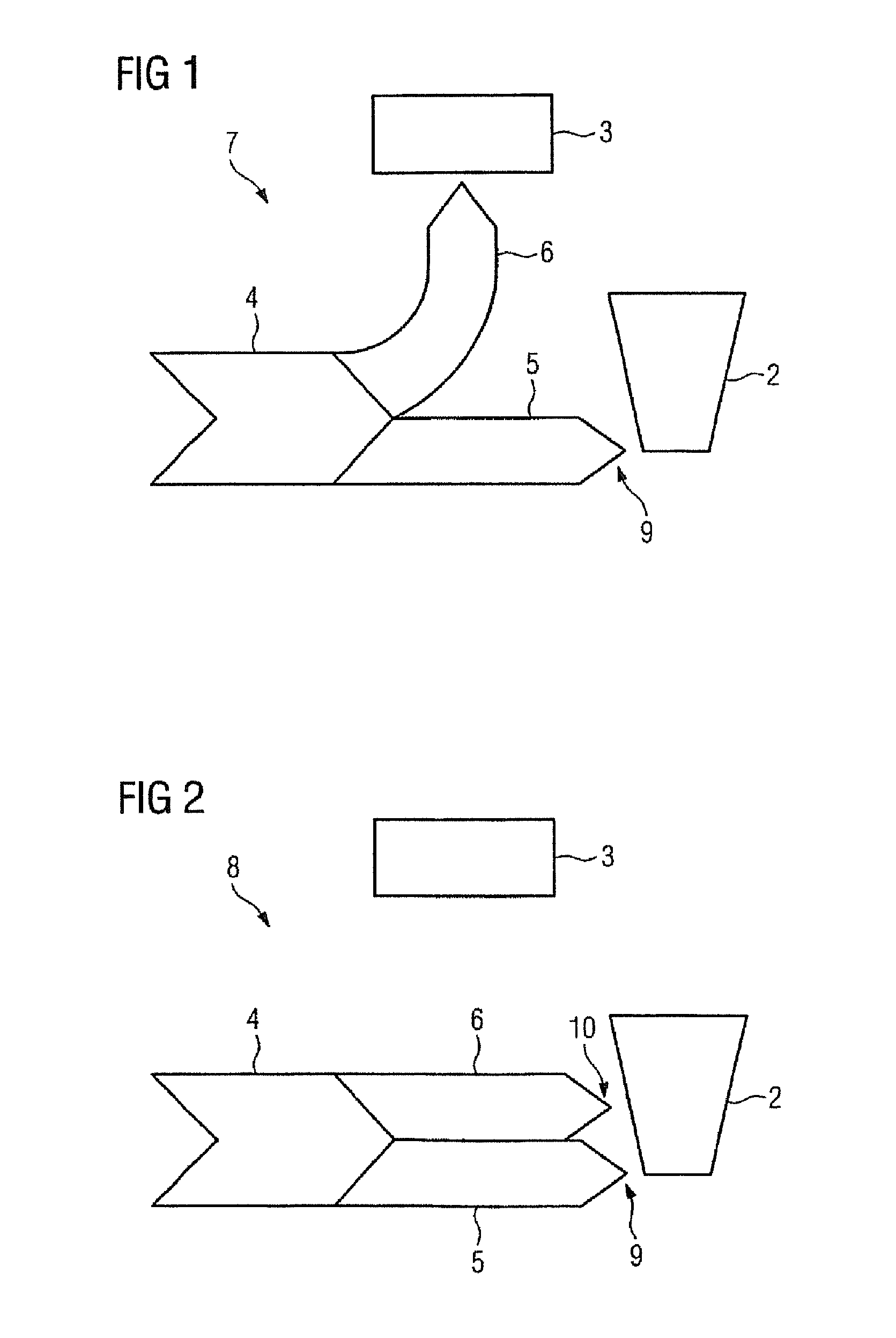
[0045]FIG. 1 shows one exemplary embodiment of an operating method for operation of a steam power station having a process steam consumer, in a first operating mode 7. The figure shows an outline sketch, illustrating a steam mass flow 4, a process steam consumer 3 and a steam turbine 2. The steam mass flow 4 is subdivided into a first mass flow element 5 and a second mass flow element 6. The first mass flow element 5 is supplied to the process steam consumer 3. The second mass flow element 6 is supplied to the steam turbine 2 in the first turbine stage 9. The steam turbine 2 is in this case designed for the second mass flow element 6.

[0046]FIG. 2 shows the operating method for operation of a steam power station having a process steam consumer, in a second operating mode 8. Analogously to FIG. 1, the figure shows a steam mass flow 4, a process steam consumer 3 and a steam turbine 2. The steam mass flow 4 is subdivided into a first mass flow element 5 and a second mass flow element 6....


PUM


Abstract

A method for operating a steam power station is provided. The steam turbine power station includes at least one steam turbine and a process steam consumer, wherein a steam mass flow is subdivided into a first partial mass flow and a second partial mass. In a first operating state, the first partial mass flow is supplied to the steam turbine and the second partial mass flow is supplied to the process steam consumer. In a second operating state, at least part of the second partial mass flow is supplied to the steam turbine at least after the first turbine stages. A steam power station is also provided.

Description

CROSS REFERENCE TO RELATED APPLICATIONS[0001]This application is the US National Stage of International Application No. PCT / EP2009 / 055332, filed May 4, 2009 and claims the benefit thereof. The International Application claims the benefits of European Patent Office application No. 08011260.0 EP filed Jun. 20, 2008. All of the applications are incorporated by reference herein in their entirety.FIELD OF INVENTION[0002]The invention relates to a method for operation of a steam power station, and in particular to a method for operation of a steam power station with different operating modes. The invention also relates to a steam power station having a steam turbine and a process steam consumer, in which the method according to the invention can be carried out.BACKGROUND OF INVENTION[0003]Steam power stations (DKW) such as this, in particular steam power stations for generation of electrical power, generally comprise a steam turbine and a fired boiler or, in the form of a gas and steam tu...

Claims


Application Information

Patent Timeline
Patent Type & Authority Patents(United States)
IPC IPC(8): F01K13/00F01K17/00
CPCF01K17/00F01K7/025Y02E20/14Y02E20/32
Inventor BEUL, ULRICHGLOS, STEFANHEUE, MATTHIASHOFBAUER, THOMASHOFFACKER, RALFLUCKEMEYER, NILSPIEPER, NORBERTSIEVERT, ROLAND
Owner SIEMENS AG
Learn More