Implantable prosthesis for replacing a human hip or knee joint and the adjoining bone sections

a technology for hip or knee joints and bone sections, applied in the field of implantable prostheses for replacing human hip or knee joints and adjoining bone sections, can solve the problems of large infection risk, inability to remain in place, and extensive operative exposure, and achieve the effect of facilitating the withdrawal of the shaft anchoring part and avoiding large resistan

Active Publication Date: 2014-07-15
BAUMGART RAINER
View PDF122 Cites 5 Cited by
  • Summary
  • Abstract
  • Description
  • Claims
  • Application Information

AI Technical Summary

Benefits of technology

[0006]The locating means provided at the shaft anchoring part thus enables directed drilling or milling of a channel being axially aligned with the shaft anchoring part inserted in the bone section and having a diameter allowing passage of the shaft anchoring part. Thereafter the attachment means at the end side of the shaft anchoring part facing away from the joint replacement part enables engagement of a tool by means of which the shaft anchoring part can be withdrawn from the cavity of the shaft replacement part through the milled channel in the bone. Subsequently a distraction medullary mail can be introduced instead of the shaft anchoring part through the milled bone channel into the cavity of the shaft replacement part and be fixed in a known manner. After the desired length growth of the bone at a previously performed osteotomy has been completed, the distraction medullary mail can be removed again through the channel in the bone and be replaced by a solid shaft anchoring part of corresponding length, which thereafter remains part of the prosthesis. All of these measures can be performed via the side of the bone facing away from the joint replacement part without requiring repeated large operations in the region of the prosthesis, so that the risk of infection is minimized.
[0012]Advantageously, a drill cutter is provided on the shaft anchoring part at the tool attachment side, which during rotation of the shaft anchoring part by means of the tool located outside the bone takes away any bone parts possibly protruding in the milled channel and thus facilitates withdrawal of the shaft anchoring part.
[0019]In the configuration according to the invention, the implantable prosthesis with its joint forming part can be designed in a conventional manner, which has significant advantages, because the prosthesis lock to the tibia component can be designed in an essentially simpler and more stable manner, and the prosthesis does not have to be decoupled any more and can remain permanently in place. Also the connection to the shaft replacement part, the length of which can be designed to be variable and as short as possible, so that only the defect produced by the resection is bridged, can be designed conventionally, for example as a cone and screw connection.
[0022]For lengthening the remaining thigh bone, first the medullary space is milled out gradually corresponding to the diameter of the envisaged distraction medullary nail up to the height of the planned osteotomy by means of a straight cannulated milling tool adapted to the set guide wire. Subsequently, the bone is cut through in a minimally invasive manner, preferably by means of a medullary space saw. The milling operation is continued until the shaft anchoring part has been reached. Therein a possibly existing curvature of the bone can be overcome, because after osteotomy the two bone segments are normally very short and align towards one another. As soon as the shaft anchoring part has been reached, a cannulated extraction tool is introduced via the guide wire, wherein a polygonal plug at the end of the cannulated extraction tool engages in a corresponding polygonal socket in the shaft anchoring part, so that rotational forces for releasing the shaft anchoring part after removal of the positive-locking connection between the shaft anchoring part and the joint replacement part and the shaft replacement part, respectively, can be transmitted. Then the guide wire is screwed out of the attachment means and a tie rod is screwed through the cannulated tool into the thread of the attachment means. Therewith also an axial force can be exerted on the shaft anchoring part and the shaft anchoring part can be extracted towards the proximal direction. Herein a drill cutter at the side of the shaft anchoring part facing away from the joint replacement part can take off smaller intramedullary obstacles. Thereafter the distraction medullary nail is introduced into the cavity of the shaft replacement part through the bone channel formed in this way. The distraction medullary nail is connected in a positive-locking manner by means of bolts or screws, on the one hand, through the provided openings to the joint replacement part and the shaft replacement part, respectively, and on the other hand to the proximal femur. If an electromotive drive with a subcutaneous receiving antenna is used, it may be required depending on the embodiment that the drive is introduced in advance into the shaft replacement part. For this, the cable is introduced in advance through the channel in the proximal femur vai the osteotomy into the opening of the joint replacement part and the shaft replacement part with the aid of a strand or a wire and led out laterally.

Problems solved by technology

In any case, however, after completion of length growth, the distraction medullary nail, which cannot remain in place for permanent shaft anchoring, must be replaced by a stable shaft anchoring part.
Exchange of a distraction medullary nail or replacement by a stable shaft anchoring part is often only possible if the joint components are decoupled, so that extensive operative exposure is required.
Thus, in addition to resection of the tumor, at least two, in most cases even three extensive surgical operations are required near the joint in the region of the prothesis, which implies a considerable risk of infection.

Method used


Image

  • Implantable prosthesis for replacing a human hip or knee joint and the adjoining bone sections
  • Implantable prosthesis for replacing a human hip or knee joint and the adjoining bone sections
  • Implantable prosthesis for replacing a human hip or knee joint and the adjoining bone sections

Examples


Embodiment Construction

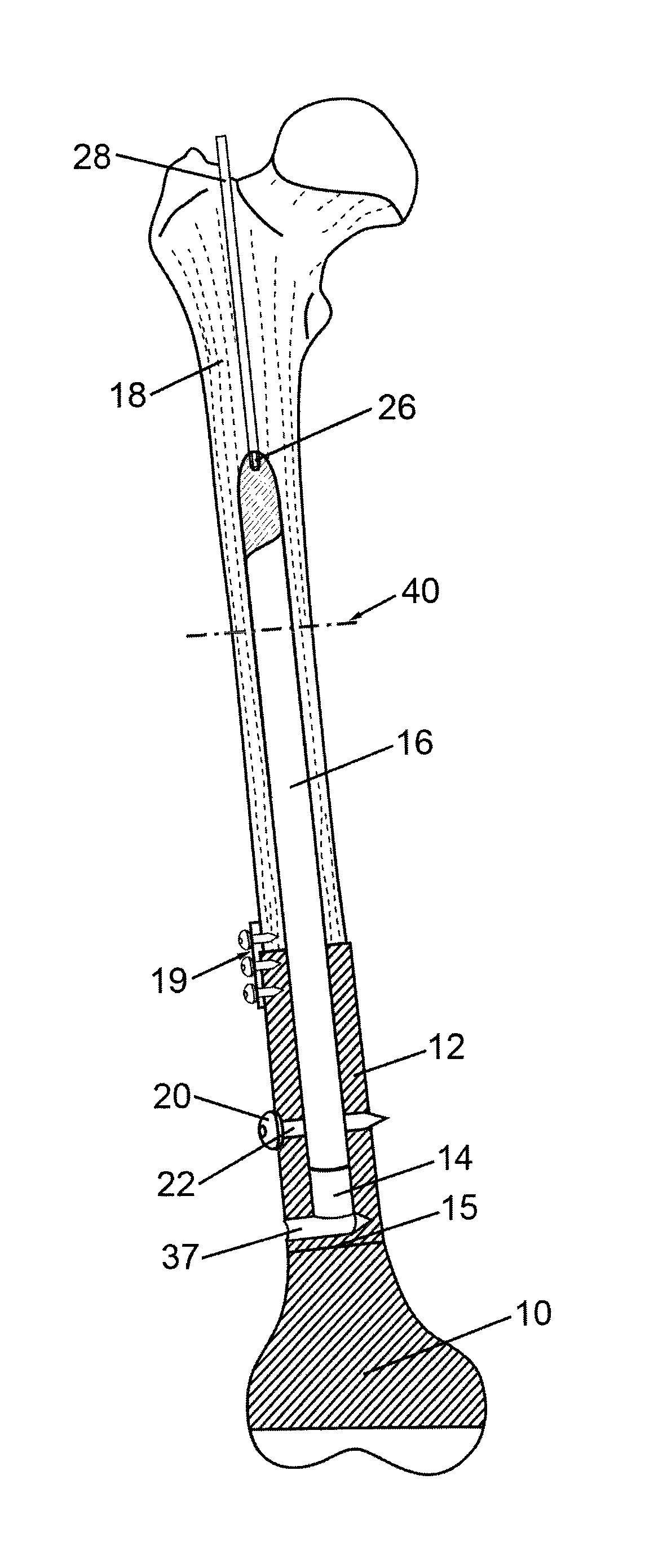
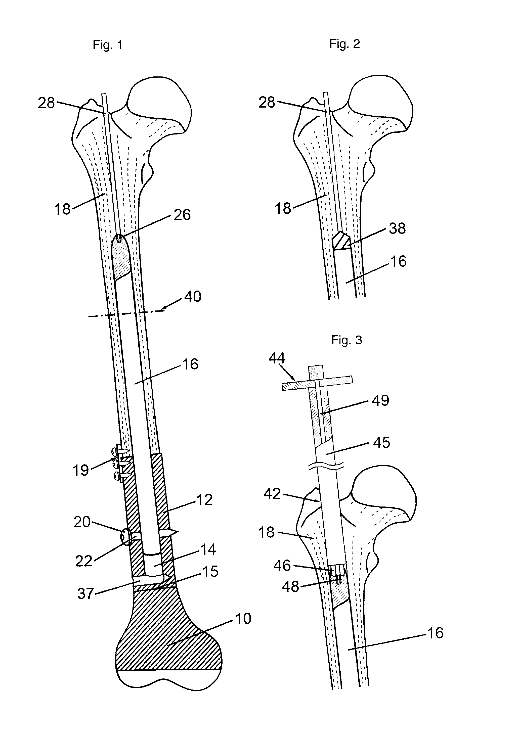
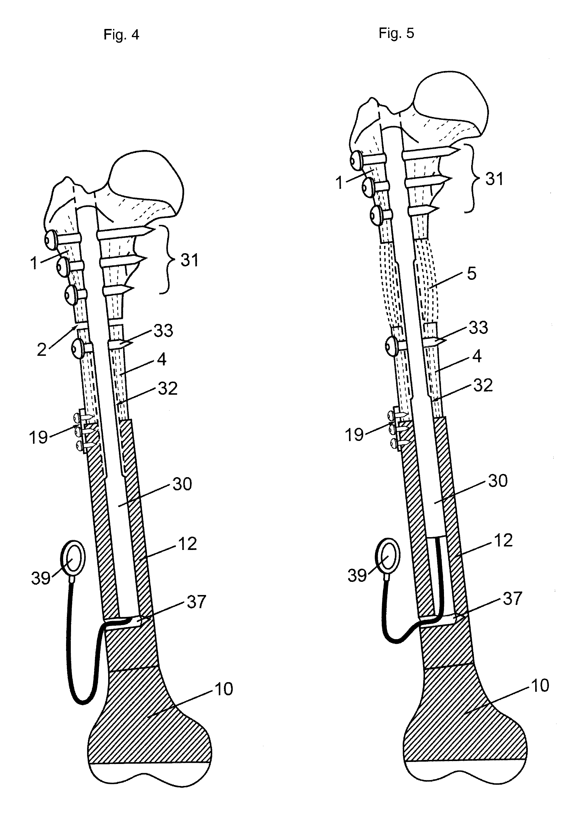
[0037]The implantable prosthesis shown in FIG. 1 comprises a joint replacement part 10, which is releasably connected to a shaft replacement part 12 for exchange purposes. The shaft replacement part 12 is connected to a bone section 18 through a plate 19 and screws.

[0038]A cavity 14 in the form of a central blind hole is formed in the shaft replacement part 12, which cavity 14 has a bottom 15 at the side of the joint replacement part 10 (in practice, the shaft replacement part 12 will surely be bored through, because appropriately the joint replacement part and the shaft replacement part are connected by a central screw) and is open at its side facing away from the joint replacement part 10. The inner wall of the cavity 14 is provided with a slide friction reducing coating. A shaft anchoring part 16 having a polished wall is inserted in the cavity 14. At the bottom 15 there is provided a lateral bore 37 in the shaft replacement part 12 for passing through a connection element, which...


PUM


Abstract

For replacing a human hip or knee joint and the adjoining bone sections, an implantable prosthesis is provided, comprising a joint replacement part (10), a shaft replacement part (12) and a rod-shaped shaft anchoring part (16) being insertable into an axial cavity (14) in the shaft replacement part (12).

Description

BACKGROUND OF THE INVENTION[0001]The present invention relates to an implantable prosthesis for replacing a human hip or knee joint and the adjoining bone sections, wherein the prosthesis comprises a joint replacement part, a shaft replacement part being connectable to the joint replacement part or integral therewith and having a central cavity, as well as a rod-shaped shaft anchoring part being insertable into the cavity. An implantable prosthesis of this kind is known from EP 1 371 346 B1.[0002]After resection of a bone tumor, the removed bone and the joint concerned can be replaced by a tumor prosthesis, and there is initially no difference in leg length. The prosthesis is anchored in the remaining bone, as described, for example, in EP 1 371 346 B1. When a difference in leg length develops due to growth, the bone can be osteotomized and the prosthesis can be provided with a distraction medullary nail instead of the shaft anchoring part for performing the callus distraction metho...

Claims


Application Information

Patent Timeline
Patent Type & Authority Patents(United States)
IPC IPC(8): A61F2/32A61F2/30
CPCA61F2/3607A61F2002/4619A61F2002/30672A61F2002/4629A61F2002/30668A61F2002/482A61F2002/3055A61F2/3859A61F2002/30607A61F2/4607A61F2002/2825A61F2002/368A61F2002/30601A61F2/482
Inventor BAUMGART, RAINER
Owner BAUMGART RAINER
Why Eureka
Try Eureka