
Synchronization of two image sequences of a periodically moving object

a technology of image sequence and periodic motion, applied in the field of synchronization of two image sequences of periodic motion objects, can solve the problems of easy misinterpretation of clinical outcomes, inability to achieve accurate comparisons which may be achieved by counting frames, and difficulty in increasing myocardium perfusion after placing the stent, etc., to achieve the effect of comparison and presentation of both sequences

Inactive Publication Date: 2014-07-15
KONINK PHILIPS ELECTRONICS NV
View PDF11 Cites 2 Cited by
  • Summary
  • Abstract
  • Description
  • Claims
  • Application Information

AI Technical Summary

Benefits of technology

The patent describes a method for comparing two different frame sequences, such as before and after a procedure, to evaluate the effectiveness of the treatment. By synchronizing these sequences and showing them simultaneously, medical professionals can accurately compare blood flow and perfusion quality before and after the procedure. This approach is particularly useful in interventional cardiology where the heart rate of the patient may differ significantly after the procedure. The synchronized presentation of both frame sequences provides a more accurate way to measure the improvement of blood flow and myocardial perfusion.

Problems solved by technology

A check if there is an increase of the arterial blood flow and an increase of myocardium perfusion after placing the stent is not easy because the heart beating rate is often different from before the treatment.
The comparison which may be achieved by counting frames is not as accurate as may be desired.
Furthermore, the comparison result achieved in this way is indirect and only provides an approximate quantitative number.
However, when the heart rate is different compared to pre-stenting, a mis-interpretation of the clinical outcome can easily occur.

Method used


Image

  • Synchronization of two image sequences of a periodically moving object
  • Synchronization of two image sequences of a periodically moving object
  • Synchronization of two image sequences of a periodically moving object

Examples


Embodiment Construction

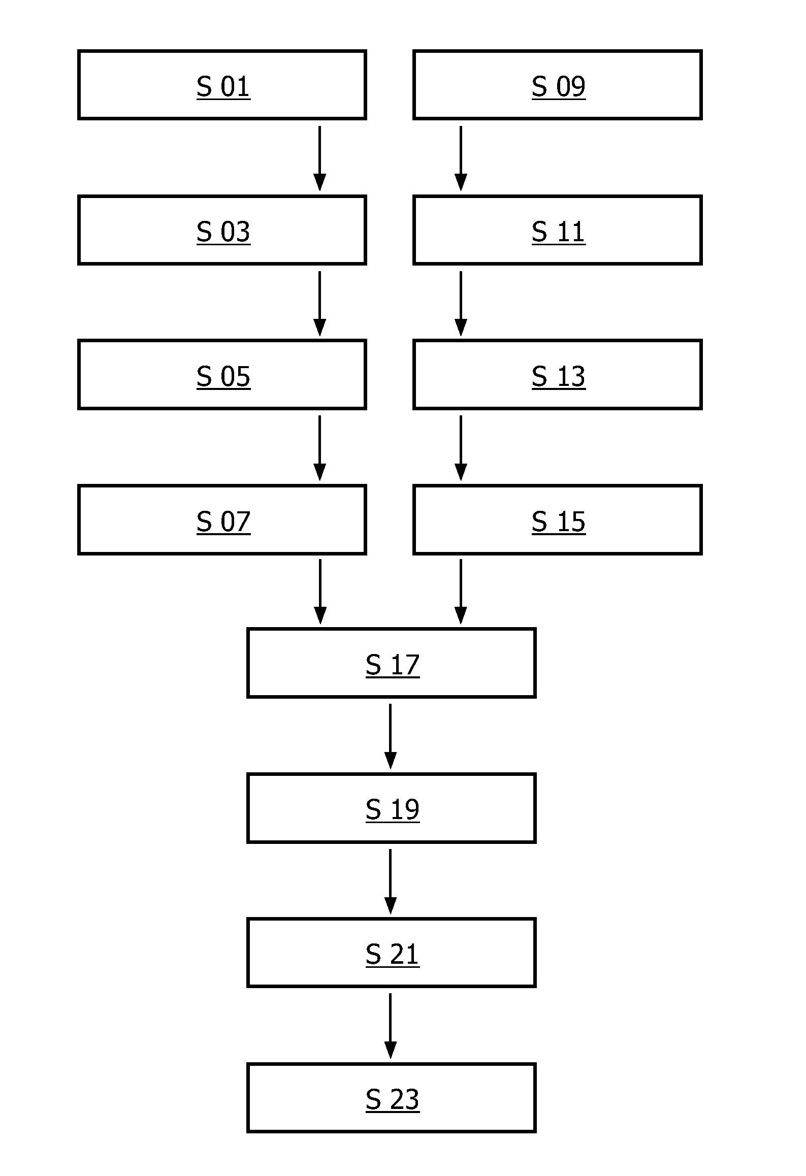
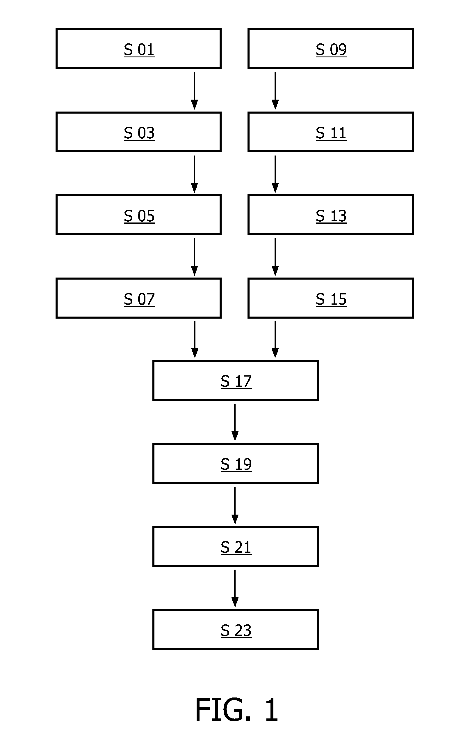
[0066]In FIG. 1 a flow diagram schematically representing a method for correlating two image sequences of a periodically moving object according to one embodiment of the present invention is presented.

[0067]In this embodiment a simple implementation of the method helps with the process of concatenating two image sequences into a single synchronized side by side view. In a first step S 01 a first frame sequence (also called a pre-stenting image sequence)

[0068]is acquired. This is done for example in connection with interventional cardiology specifically in connection with catheter-based treatment of heart diseases. For example, the first frame sequence is acquired before a therapy as for example a Percutaneous Transluminal Coronary Angioplasty (PTCA) is conducted. E.g. the first frame sequence is acquired before a device such as a stent is placed in a coronary artery to improve the flow of blood in the vessels and to improve the delivery of oxygen rich blood to the microvasculature o...


PUM


Abstract

A method and an apparatus for correlating two image sequences of a periodically moving object with respect to the periodicity is described. A first frame sequence of the object moving with the first periodicity is acquired. Therein the first frame sequence comprises at least one cycle of motion. A second frame sequence of the object moving with the second periodicity is acquired. Therein the second frame sequence comprises at least one cycle of motion. The first and the second frame sequences are synchronized with respect to the respective periodicity such that same phases of motion of the periodically moving object are correlated to be presented simultaneously. The present invention allows to compare sequences representing a periodical motion with a different number of frames in each of the sequences for the same cycle of motion. Thereby, e.g. image sequences of a beating heart acquired before and after a therapy may be presented in a synchronized way and therefore may be easily compared.

Description

FIELD OF THE INVENTION[0001]The present invention relates to the field of correlating two image sequences of a periodically moving object with respect to the periodicity. Particularly, the present invention relates to a method and an apparatus for correlating to image sequences of a periodically moving object. Furthermore, the present invention also relates to a computer program element adapted for controlling such method when executed on a computer and to a computer-readable medium on which such computer program element is stored.BACKGROUND OF THE INVENTION[0002]In many areas of science it may be important to supply image sequences of an object of interest to a viewer. In the case that the object of interest is moving periodically it may be interesting to compare image sequences acquired at different points in time. Particularly in some areas of medicine it may be important to compare the behaviour of a moving organ as for example the heart or the lungs before and after a certain e...

Claims


Application Information

Patent Timeline
Patent Type & Authority Patents(United States)
IPC IPC(8): G06K9/32G06K9/00G06T7/00
CPCG06T7/0024G06T2207/10016G06T2207/30048G06T7/30
Inventor BRUIJNS, ANTONIUS JOHANNES CORNELIUSLUIJENDIJK, JOHANNES ALBERT
Owner KONINK PHILIPS ELECTRONICS NV
Learn More