
Pelvic frame and walking assistance device using the same

a technology of pelvic frame and pelvic frame, which is applied in the direction of walking aids, physical therapy, chiropractic devices, etc., can solve the problems of unsatisfactory conventional arrangement in this regard, twisting of a part of the pelvis frame, and previously proposed pelvis frame that were not totally satisfactory in this regard, and achieves a favorable fit effect on the user

Active Publication Date: 2014-07-22
HONDA MOTOR CO LTD
View PDF8 Cites 7 Cited by
  • Summary
  • Abstract
  • Description
  • Claims
  • Application Information

AI Technical Summary

Benefits of technology

[0007]In view of such problems of the prior art, a primary object of the present invention is to provide a pelvic frame for a working assistance device that can adequately support the reaction of the force (torque) produced by the power generator and favorably fit on the user without causing any discomfort.
[0008]A second object of the present invention is to provide a pelvic frame for a working assistance device that facilitates the wearing of the pelvic frame by a user.
[0011]Because the two free end of the main frame are joined by the stabilizer members in cooperation with the abdominal belt, the stiffness and mechanical strength of the main frame is effectively enhanced, and the deformation of the pelvic frame during use can be minimized. The reduction in the deformation of the pelvic frame contributes to the comfort of the user.
[0012]Also, as the stabilizer members hold up the corresponding parts of the abdominal belt in readily accessible positions in spite of the flexibility of the abdominal belt, the wearing and removing of the pelvic frame is simplified.
[0013]According to a preferred embodiment of the present invention, each stabilizer member is substantially more flexible in lateral bending than in vertical bending. Thereby, the stabilizer member is given with a flexibility in the lateral direction for an improved fit on the body of the user and a stiffness required for the stabilizer member to withstand the compressive and other loads may be applied thereto during use.
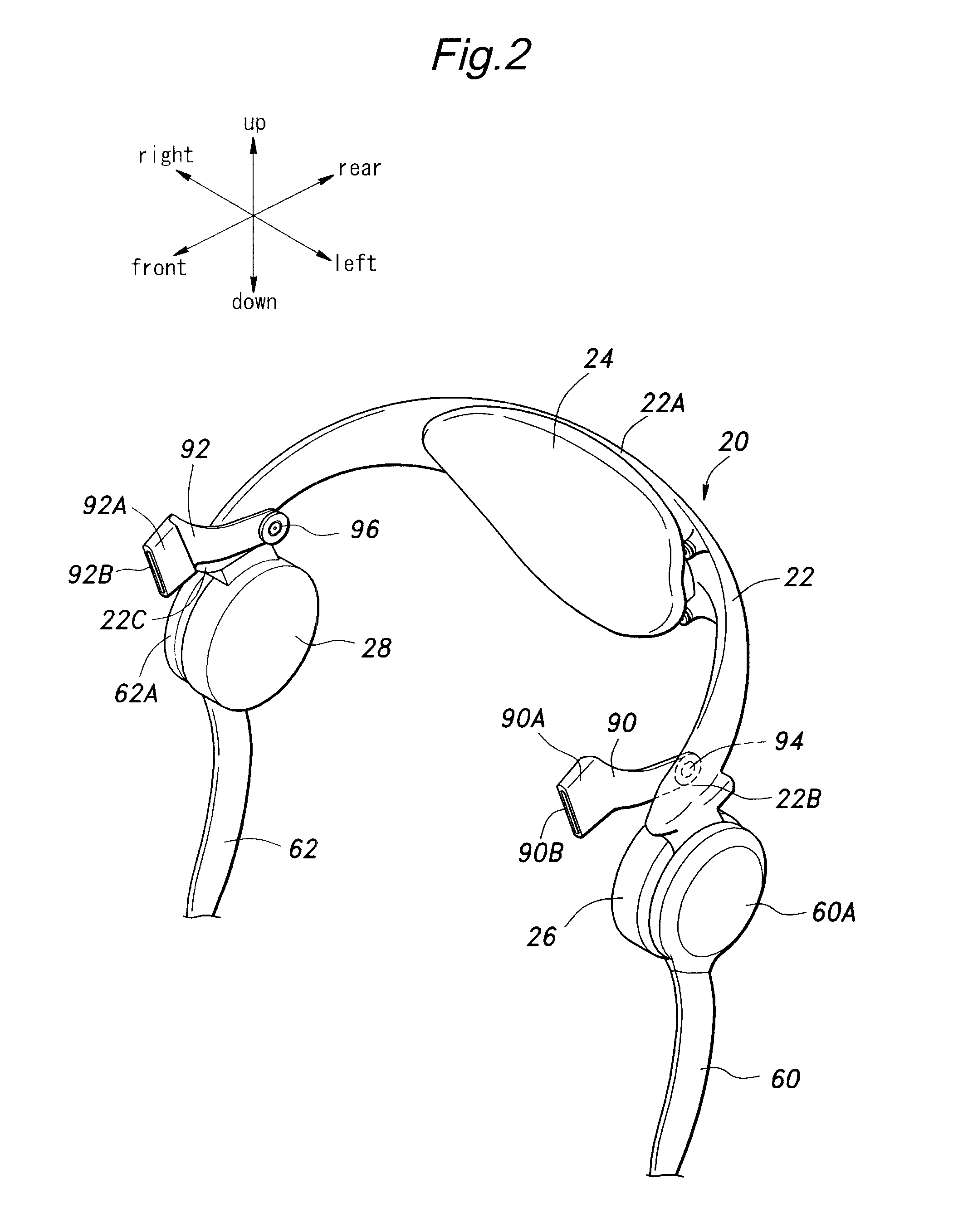
[0014]According to a particularly preferred embodiment of the present invention, each stabilizer member comprises a plate member having a vertically elongated cross section, and a substantially vertically oriented major plane, and the base end of each stabilizer member is pivotally connected to the main frame so as to be rotatable around an axial line extending perpendicular to the major plane of the stabilizer member. Furthermore, each stabilizer member may extend in an upwardly oblique direction from the base end thereof to the free end thereof for a favorable support of the main frame in cooperation with the abdominal belt.

Problems solved by technology

However, the conventional arrangement was not totally satisfactory in this regard.
More specifically, as the pelvic frame had a limited capacity in preventing the rotation of the pelvic frame around the pivot center of the hip joint when the pelvic frame is worn by the user, the reaction of the walking assistance force produced by the power generator is not adequately supported, and this caused the twisting of a part of the pelvic frame.
The pelvic frame is desired to be worn and removed with as little effort as possible, but the previously proposed pelvic frames were not totally satisfactory in this regard.

Method used


Image

  • Pelvic frame and walking assistance device using the same
  • Pelvic frame and walking assistance device using the same
  • Pelvic frame and walking assistance device using the same

Examples


Embodiment Construction

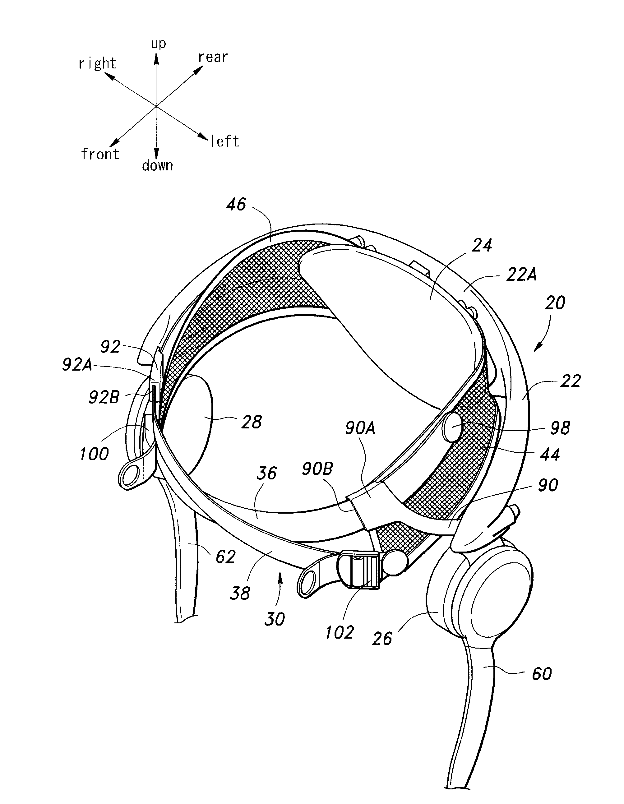
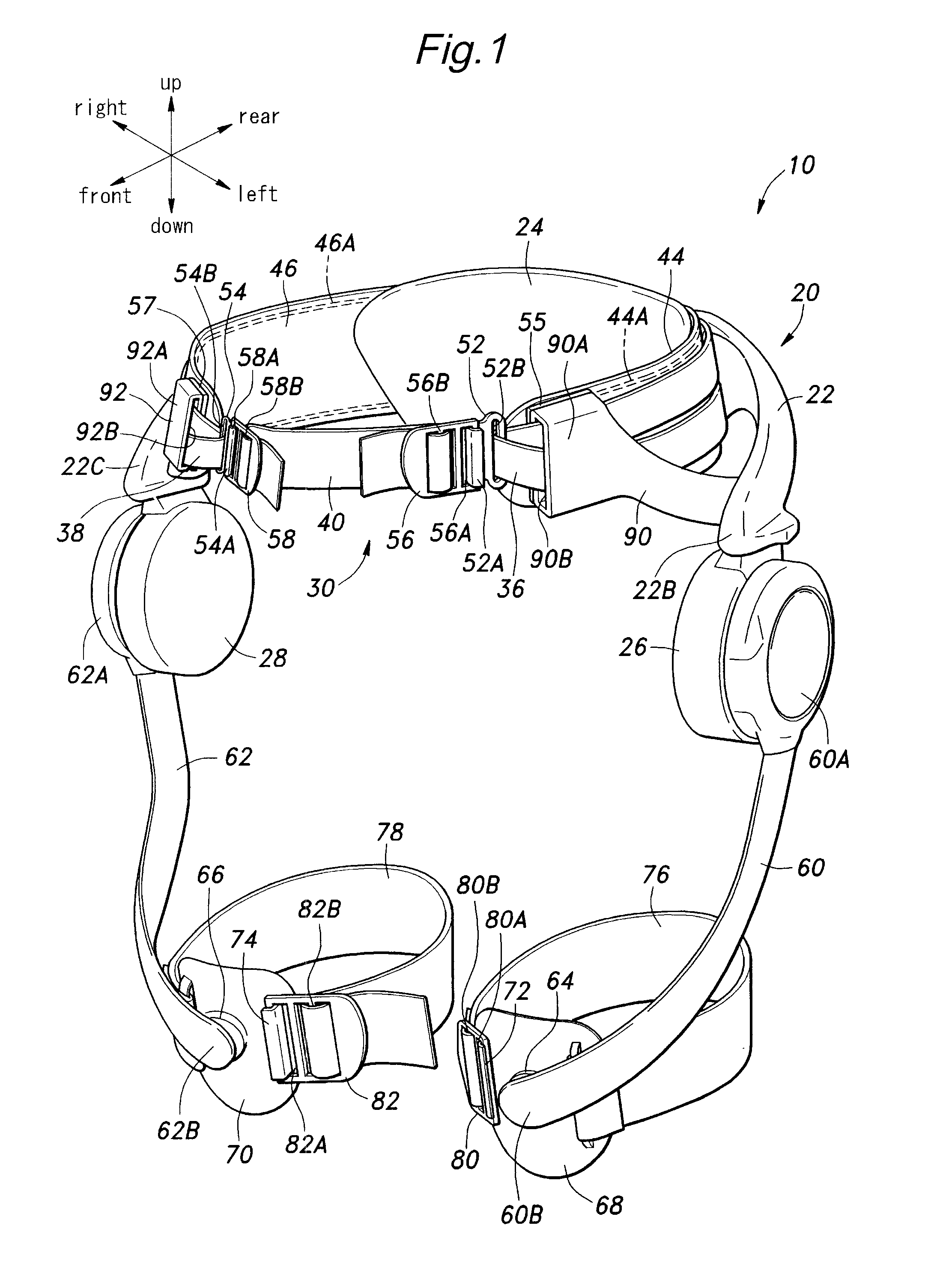
[0021]An embodiment of the walking assistance device of the present invention will now be described in the following with reference to FIGS. 1 and 2. In the succeeding description, the direction of the walking assistance device will be based on the directional arrows shown in each of the drawings. When the device is worn by the user, the front and back directions of the walking assistance device coincide with the coronal axis, while the left and right directions coincide with the sagittal axis.

[0022]The walking assistance device 10 is provided with a pelvic frame 20. The pelvic frame 20 is configured to be worn on the pelvic part of the user, and includes a main frame 22 that extends outwardly from a lower back part of the user to either side of the pelvic part to form a C-shape when viewed in plan view. The main frame 22 is formed with molded plastic material such as polyamide resin, glass fiber reinforced plastic material, carbon fiber reinforced plastic material or other material...


PUM


Abstract

A pelvic frame (20) for a walking assistance device (10) is configured to be worn on a pelvic part of a user, and comprises a main frame (22) extending from a lower back of the user to either side of the user, an abdominal belt (30) attached to the main frame at base ends thereof, extending along an inner periphery of the main frame (22) and configured to be detachably passed along an abdominal part of the user, and a pair of stabilizer member (90, 92) each having a base end attached to a free end part of the main frame (22) and a free end engaging the abdominal belt (30). Because the two free end of the main frame (22) are joined by the stabilizer members (90, 92) in cooperation with the abdominal belt (30), the stiffness and mechanical strength of the main frame (22) is effectively enhanced, and the weight of the main frame and material cost can be minimized. Also, the deformation of the pelvic frame (20) during use can be minimized, and this contributes to the comfort of the user. Also, as the stabilizer members (90, 92) hold up the corresponding parts of the abdominal belt (30) in readily accessible positions in spite of the flexibility of the abdominal belt (30), the wearing and removing of the pelvic frame (20) is simplified.

Description

TECHNICAL FIELD[0001]The present invention relates to a pelvic frame for a walking assistance device and a walking assistance device using the same, and in particular to a pelvic frame for a walking assistance device configured to apply a walking assistance force generated by a power generator to a lower limb of a user and a walking assistance device using the same.BACKGROUND OF THE INVENTION[0002]Previously proposed is a walking assistance device that includes a power generator such as an electric motor to apply a walking assistance force to a lower limb of a user for the purposes of assisting the walking movement of the user, and / or rehabilitating the walking impairment of the user. See Japanese laid open patent publications JP2006-320351A and JP2008-134086A (patent documents 1 and 2), for instance.[0003]Such a walking assistance device typically includes a pelvic frame consisting of a C-shaped main frame configured to be worn on a pelvic part of the user and extending from a lowe...

Claims


Application Information

Patent Timeline
Patent Type & Authority Patents(United States)
IPC IPC(8): A61H3/00A61H1/02
CPCA61H3/00A61H2201/165A61H2201/5061A61H1/0244A61H2201/5069
Inventor TAKAHASHI, HIDEAKISHIMIZU, HIDEO
Owner HONDA MOTOR CO LTD
Learn More