Apparatus, method, and system for independent aiming and cutoff steps in illuminating a target area

a target area and cutoff step technology, applied in the direction of fixed installation, lighting and heating apparatus, lighting support devices, etc., can solve the problems of affecting the effective projected area of the fixture, wasteful and potential nuisance, limitations of approach, etc., to reduce epa, increase lighting uniformity, and increase glare control

Active Publication Date: 2014-07-29
MUSCO
View PDF68 Cites 47 Cited by
  • Summary
  • Abstract
  • Description
  • Claims
  • Application Information

AI Technical Summary

Benefits of technology

[0007]Envisioned is a compact lighting fixture designed to accommodate a plurality of light sources, and means and methods for independent light directing and light redirecting thereof such that a complex target area may be adequately illuminated with increased glare control, reduced EPA, and increased lighting uniformity as compared to at least most conventional floodlight-type fixtures for sports lighting applications.
[0010]According to another aspect of the present invention, a lighting fixture comprising a plurality of said modular apparatuses is adjusted relative to its elevation point above a target area to provide some aiming of the light projected therefrom. Each modular apparatus may then be adjusted relative to its connection point to the lighting fixture to provide further aiming of the light projected therefrom. Following this, or in addition, each light source and each visor in each modular apparatus may be adjusted selectively and independently of one another so to provide desired aiming and cutoff. In this manner, the light projected from each modular apparatus contributes a portion of the overall lighting of the target area; this permits flexibility in addressing such things as glare prevention and lighting uniformity.

Problems solved by technology

This light, commonly referred to as spill light, is wasteful and a potential nuisance (e.g., to spectators in bleachers 515) or hazardous (e.g., to drivers on a road adjacent to target area 5).
There are limitations to the approach illustrated in FIGS. 1A-C.
For example, the adjustment of fixture 4 relative to pole 6 and addition of a visor may adversely affect the fixture's effective projected area (EPA) which may increase wind loading.
An increased EPA may require a more substantial pole or more robust means of affixing the fixture to the pole, both of which may add cost.
This poses a problem because when multiple smaller light sources (e.g., LEDs) are housed in fixture 4, a single visor may not adequately redirect all spill light back onto target area 5 or provide a distinct cutoff; this can result in uneven illumination, shadowing effects, or glare which can be a nuisance or potentially dangerous (e.g., affecting playability on the field).

Method used


Image

  • Apparatus, method, and system for independent aiming and cutoff steps in illuminating a target area
  • Apparatus, method, and system for independent aiming and cutoff steps in illuminating a target area
  • Apparatus, method, and system for independent aiming and cutoff steps in illuminating a target area

Examples


embodiment 1

B. Exemplary Method and Apparatus Embodiment 1

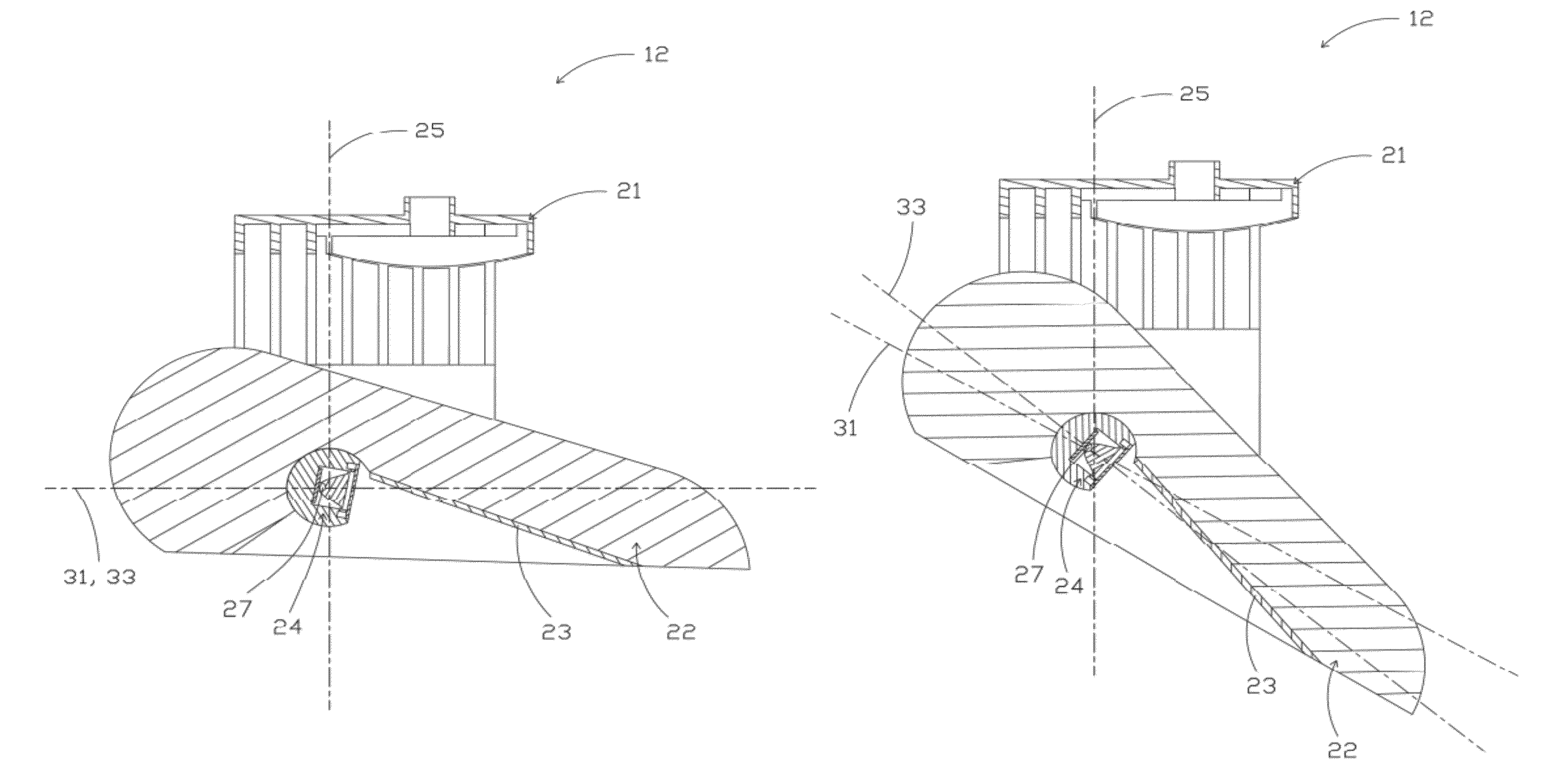
[0024]A specific example of the aforementioned modular apparatus is illustrated in FIGS. 2A-7B. With regards to FIGS. 2A-F, modular apparatus 12 may generally be understood as comprising a housing 22 which is formed to receive both a visor 23 and an enclosure 24, the latter of which is adapted to house a plurality of light sources 27 with associated optics 28 (see, e.g., FIG. 3A). An outer lens 29 seals against the open face of enclosure 24 (see FIG. 2F)—e.g., by gluing or taping—so to protect the light sources against dust, vandalism, or other undesirables and, if desired, may include an anti-reflection coating so to preserve transmission efficiency.

[0025]Visor 23 is formed from a highly reflective material (e.g., aluminum processed to high reflectivity) and is affixed to the inner surface (i.e., the non-finned surface) of housing 22; see FIG. 2F. It is of note that visor 23 may be bolted, glued, or otherwise affixed directly to the inn...


PUM

PropertyMeasurementUnit
rotationaaaaaaaaaa
cutoff angleaaaaaaaaaa

Abstract

A lighting fixture is presented comprising a plurality of modular apparatuses wherein each modular apparatus comprises one or more light sources and one or more light directing or light redirecting devices. Methods of adjusting one or more components of said lighting fixture about one, two, or three axes are presented whereby the lighting needs of a target area—even one of complex shape—may be addressed and in a manner that promotes compact fixture design with low effective projected area (EPA) without sacrificing transmission efficiency of the light sources.

Description

CROSS-REFERENCE TO RELATED APPLICATIONS[0001]This application claims priority under 35 U.S.C. §119 to provisional U.S. Application Ser. No. 61 / 492,426, filed Jun. 2, 2011, hereby incorporated by reference in its entirety.I. BACKGROUND OF THE INVENTION[0002]The present invention generally relates to means and methods by which a target area is adequately illuminated by one or more lighting fixtures. More specifically, the present invention relates to improvements in the design and use of lighting fixtures such that the steps of aiming and cutoff of light projected from said lighting fixtures may be separated so to gain more flexibility in addressing the lighting needs of a particular application without adversely affecting the size, effective projected area, or efficiency of the lighting fixtures.[0003]It is well known that to adequately illuminate a target area—particularly a target area of complex shape—a combination of light directing (e.g., aiming, collimating) and light redirecti...

Claims


Application Information

Patent Timeline
Patent Type & Authority Patents(United States)
IPC IPC(8): F21S4/00F21V21/00F21V7/00F21V19/02
CPCF21V19/02F21V7/00F21V14/00F21V7/0025F21Y2101/02F21Y2103/003F21W2131/105F21V21/00F21S8/088F21V7/05F21V21/30F21S4/00F21V29/267F21V14/02F21V29/73F21Y2103/10F21Y2115/10Y10T29/49826F21S2/005F21V5/04F21V9/00F21V13/14H05B47/10
Inventor GORDIN, MYRONBOYLE, TIMOTHY J.
Owner MUSCO
Why Eureka
Try Eureka