
Synchronization method for current differential protection

a current differential and synchronization method technology, applied in the field of power systems, can solve the problems of channel symmetry status, signal of gps not always reliable enough, and not always symmetrical in practical terms

Active Publication Date: 2014-07-29
HITACHI ENERGY LTD
View PDF12 Cites 7 Cited by
  • Summary
  • Abstract
  • Description
  • Claims
  • Application Information

AI Technical Summary

Benefits of technology

This method ensures reliable synchronization of current differential protection measurements, even under asymmetrical communication channels or unreliable GPS signals, and effectively handles both heavy and no load conditions, as well as multiple-terminal systems and synchronization errors beyond half a cycle, enhancing the reliability of power system protection.

Problems solved by technology

However, the reliability of echo method depends on the symmetry of communication channels and it is not always symmetrical in practical.
And the signal of GPS is not always reliable enough.
It will influence the reliability of current differential protection markedly and even may cause mal-operation in some conditions.
The main problem of existing echo method is that its operation is severely affected by the channel symmetry status.
It causes new problems to optical fiber current differential protection for transmission lines.
Thus once the asymmetrical channel switching, the delays of sending and receiving channels are no longer equal, and thus the reliability of protection devices will be affected due to the data out of synchronization.
The main problem of synchronization by GPS is that GPS signal and device is not reliable enough to meet the requirement of protection system in practical, although GPS can provide accurate, absolute and synchronized time for all substations theoretically.
But phase angle of load currents in light load or no load conditions cannot be measured accurately.
Thus, the load current based synchronization method cannot deal with light load or no load conditions.
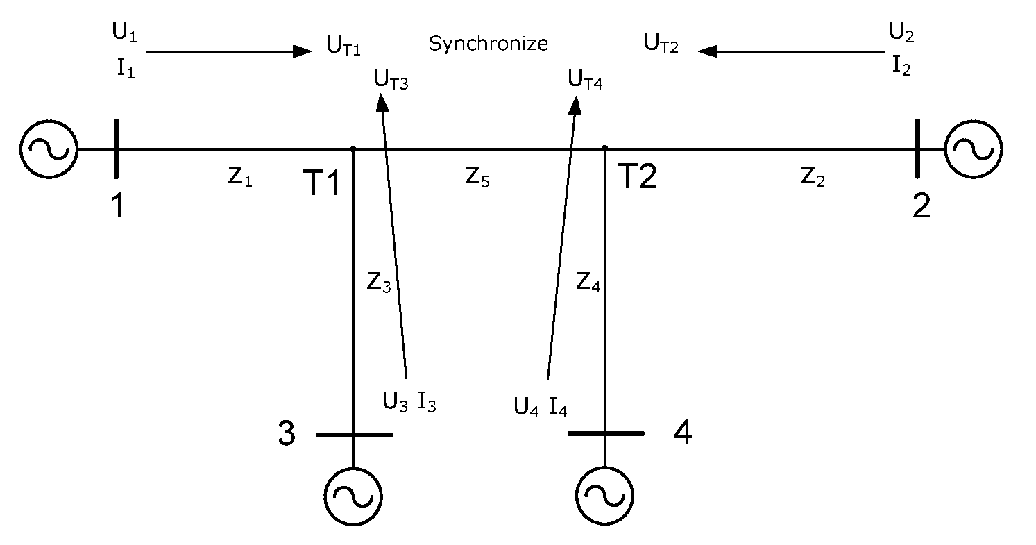
And another shortcoming of this method is that it can only deal with two-terminal transmission line and cannot synchronize the measurements for the transmission line with more than two terminals.
Thus, the unique relative angle difference among these vectors cannot be determined.
That means the measurements for the transmission line with more than two terminals by the said load current based synchronization method cannot be synchronized.
And in addition, these patens based on load currents have not considered the problem of more than half cycle synchronization error.
Because the load current is periodical wave, if the synchronization error may be bigger than half cycle, the synchronization method cannot decide which direction is the right one for correcting the error.
In summation, for all the methods in above mentioned patents, although existing load current based synchronization method will not be influenced by asymmetrical channels, they cannot deal with light load or no load conditions, cannot deal with transmission lines with more than two terminals, and cannot deal with more than half cycle synchronization error.
However, the improved echo method may have the problem of accumulative error if there is lots of channel switching.

Method used


Image

  • Synchronization method for current differential protection
  • Synchronization method for current differential protection
  • Synchronization method for current differential protection

Examples


embodiment

Pre-Fault Embodiment

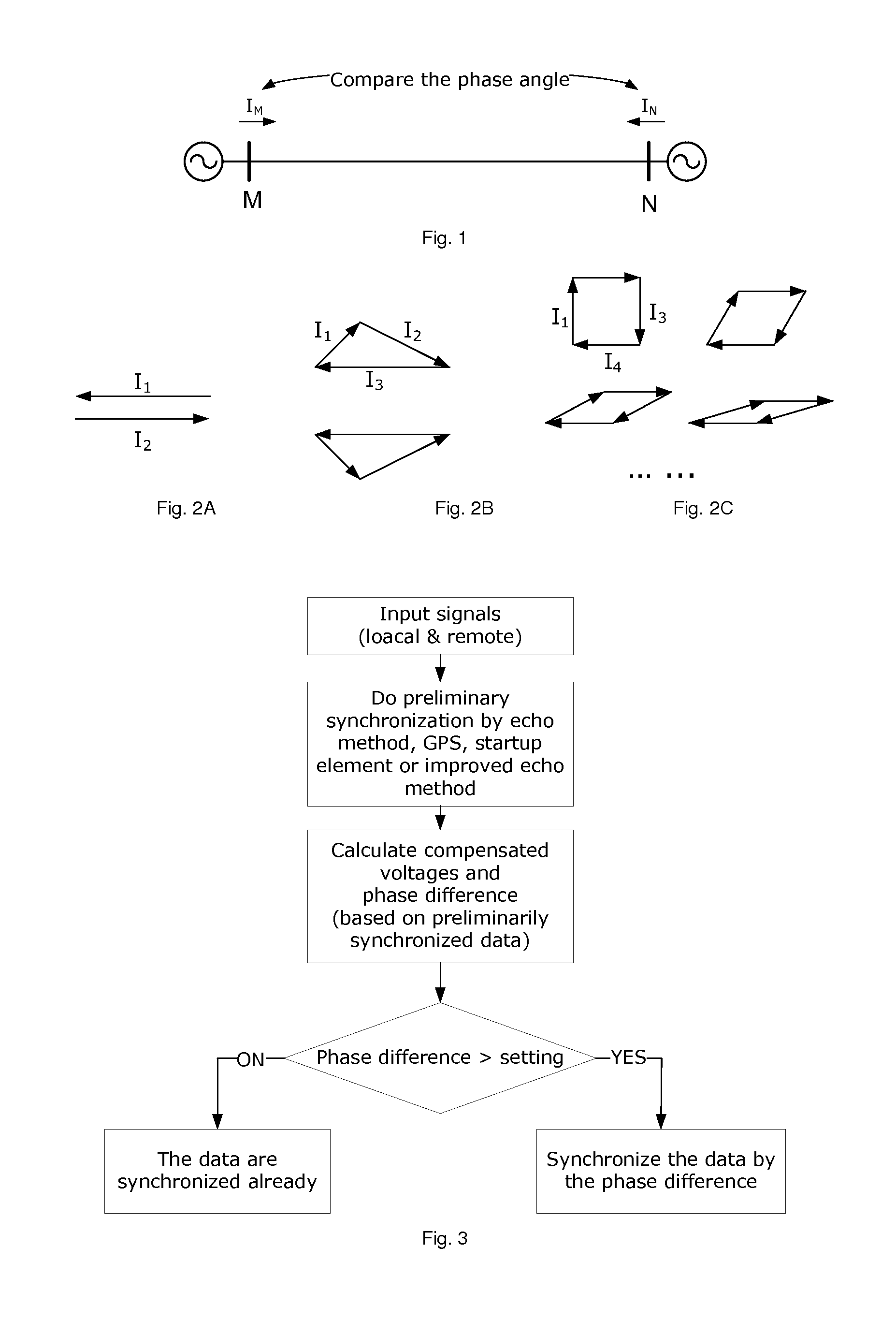
[0041]FIG. 3 is the conceptual flowchart of the first preferred embodiment. In this preferred embodiment, the current and voltage of each of the terminals are measured before a fault and the current and voltage of each of the terminals are vectors. The method of the current and voltage of each of the terminals in sampling values is also provided.

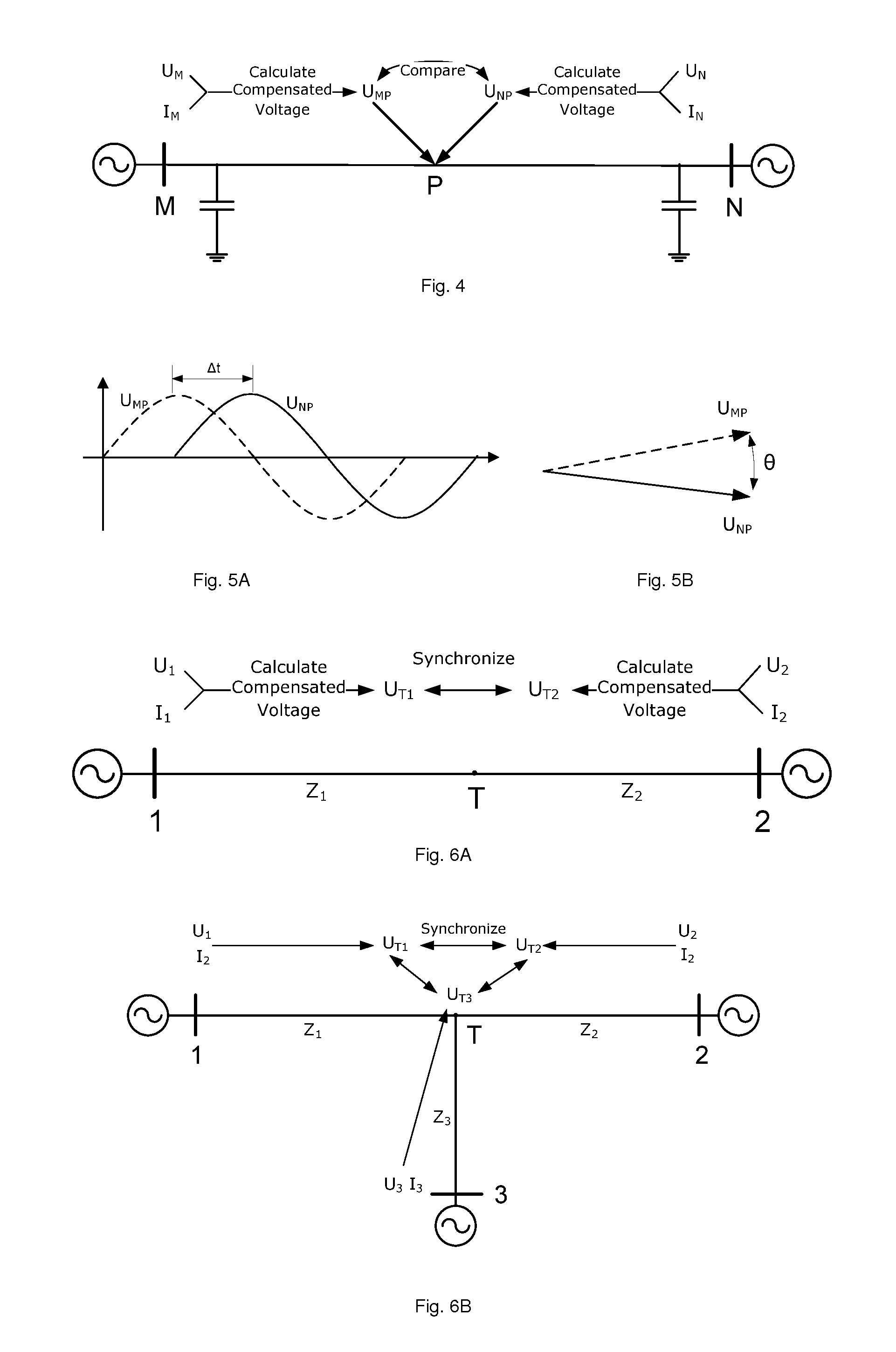
[0042]In the pre-fault status, the compensated voltages on the same certain point along the transmission line calculated from all terminals should be the same with each other. That means that if the voltage at the same point is calculated by the measurements from different terminals, these calculated (compensated) voltages should be the same, including the phase angle and wave shift. If the phases of compensated voltages are different from each other, it means the data synchronization (communication channel becomes asymmetrical or GPS signal becomes unreliable) is wrong. And the phase difference or wave shift between thes...


PUM


Abstract

A synchronization method for current differential protection comprises: selecting a point on the transmission line protected by the current differential protection; measuring the current and the voltage of each of the terminals of said transmission line; calculating the compensating voltage at the selected point respectively according to the measured current and the voltage of the each terminal; detecting and calculating the synchronization error by comparing all the compensating voltages.

Description

RELATED APPLICATION[0001]This application is a national filing of PCT application Serial No. PCT / CN2010 / 078562, filed Nov. 9, 2010.FIELD OF THE INVENTION[0002]This invention relates to the field of power system, and more particularly to a synchronization method used for current differential protection.BACKGROUND OF THE INVENTION[0003]Data synchronization is very important for the applications in power system, especially for current differential protection. Some external synchronization mechanism such as echo method or GPS is used widely by the protection system to ensure the data synchronization in practical applications. However, the reliability of echo method depends on the symmetry of communication channels and it is not always symmetrical in practical. And the signal of GPS is not always reliable enough. It will influence the reliability of current differential protection markedly and even may cause mal-operation in some conditions.[0004]The main problem of existing echo method ...

Claims


Application Information

Patent Timeline
Patent Type & Authority Patents(United States)
IPC IPC(8): H03L7/00
CPCH03L7/08H02H3/283H02H3/30H02H7/263H04J3/0667
Inventor LI, YOUYISU, BINYANG, YINGEINARSSON, TORBJORNGAJIC, ZORAN
Owner HITACHI ENERGY LTD
Learn More