
System and method for indoor location tracking using pseudo GPS signal transmitter

a technology of indoor location and signal transmitter, which is applied in the field of indoor location tracking using a pseudo gps signal transmitter, can solve the problems of not being able to actually implement this technology, being less economical than a gps system, and unable to calculate the location, so as to achieve high-precision time synchronization and reduce infrastructure costs

Inactive Publication Date: 2014-07-29
ELECTRONICS & TELECOMM RES INST
View PDF11 Cites 10 Cited by
  • Summary
  • Abstract
  • Description
  • Claims
  • Application Information

AI Technical Summary

Benefits of technology

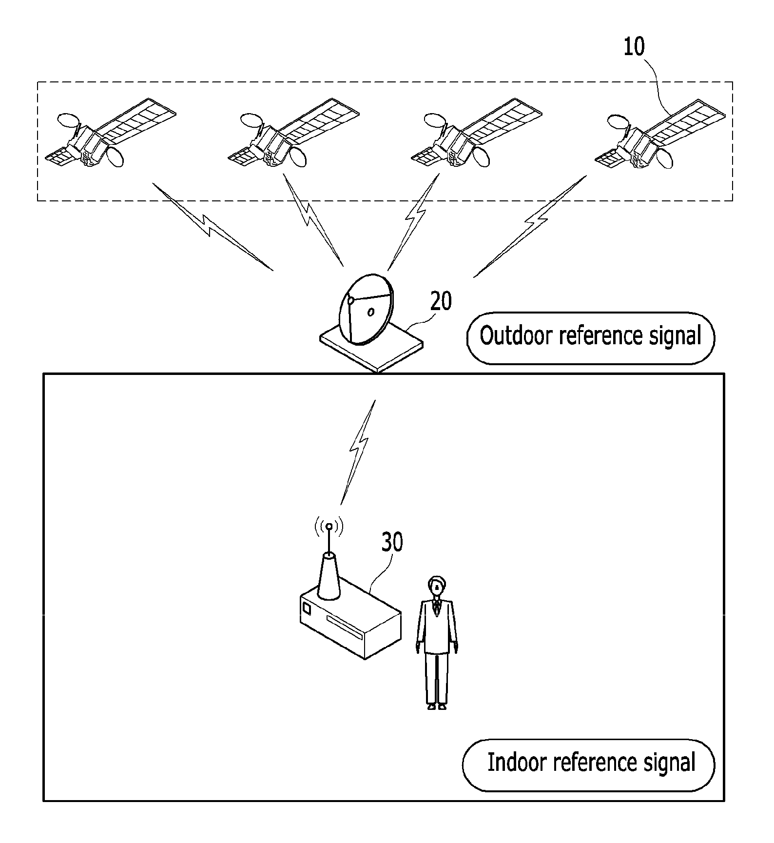
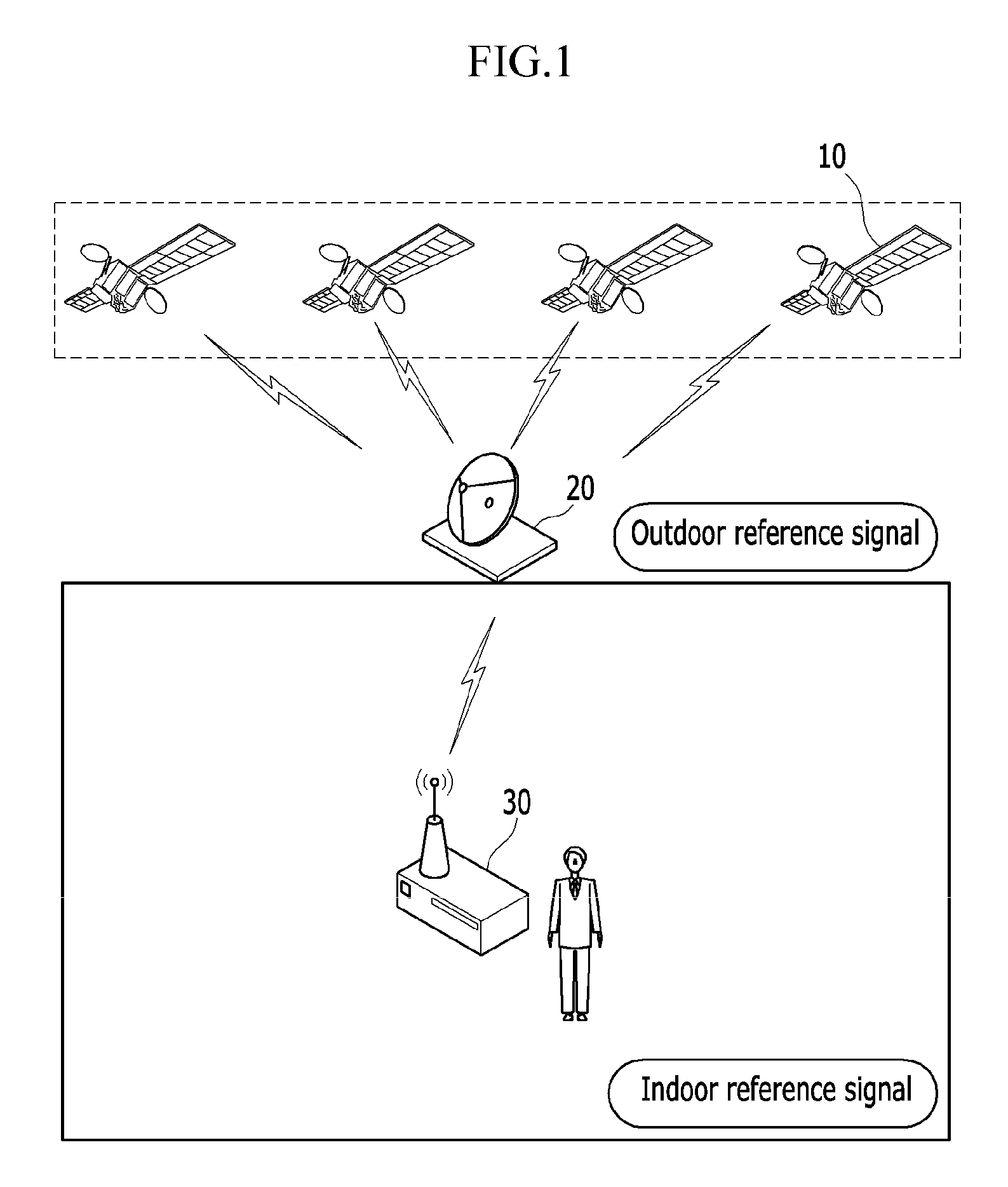
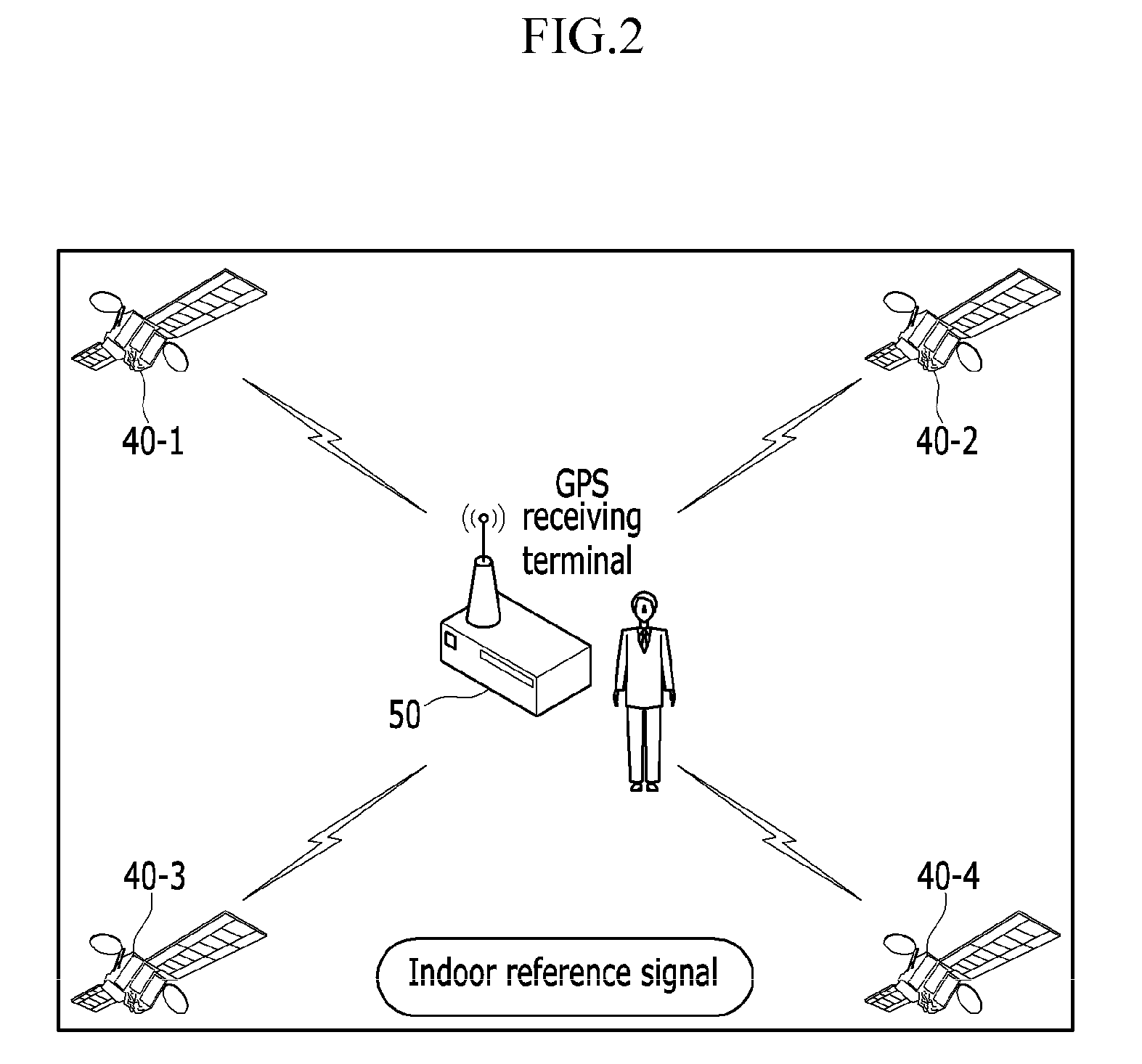
The invention allows GPS tracking to be used indoors by using a pseudo GPS signal. This is achieved by synchronizing the time of the pseudo GPS signal transmitter with a GPS signal from a satellite. This high-precision synchronization eliminates the need for multiple indoor pseudo satellites. By transmitting location and time information from a transmitting antenna to other antennas through a switching method, the same effect can be achieved as using multiple pseudo satellites with a single pseudo GPS signal transmitter. This reduces infrastructure costs. Additionally, the invention allows for exact location tracking in indoors compared to traditional indoor location tracking systems as GPS signals from a satellite are received and relayed to the indoors.

Problems solved by technology

This is because, for indoor spaces, a GPS signal is severely attenuated through building walls or the like, and this causes difficulties in acquiring the GPS signal in poor propagation environments, thereby making location calculation impossible.
However, such an indoor wireless location determination technology requires an infrastructure dedicated for wireless communication, and is therefore less economical compared to a GPS system.
This causes many difficulties in actually putting this technology into practice and widening the application range.

Method used


Image

  • System and method for indoor location tracking using pseudo GPS signal transmitter
  • System and method for indoor location tracking using pseudo GPS signal transmitter
  • System and method for indoor location tracking using pseudo GPS signal transmitter

Examples


Embodiment Construction

[0025]In the following detailed description, only certain exemplary embodiments of the present invention have been shown and described, simply by way of illustration. As those skilled in the art would realize, the described embodiments may be modified in various different ways, all without departing from the spirit or scope of the present invention. Accordingly, the drawings and description are to be regarded as illustrative in nature and not restrictive. Like reference numerals designate like elements throughout the specification.

[0026]Throughout the specification, unless explicitly described to the contrary, the words “comprise” and “include” and variations such as “comprises”, “includes”, “comprising”, or “including” will be understood to imply the inclusion of stated elements but not the exclusion of any other elements.

[0027]In the specification, a terminal may indicate a mobile station (MS), a mobile terminal (MT), a subscriber station (SS), a portable subscriber station (PSS),...


PUM


Abstract

To track the location of a terminal in an indoor space by using a pseudo GPS signal transmitter, a GPS signal sent from an artificial satellite is received, and a clock signal of the artificial satellite is extracted from the received GPS signal to perform synchronization with the artificial satellite. Once synchronization with the artificial satellite is performed, a pseudo GPS signal is generated, and the transmission time of the pseudo GPS signal is controlled. The GPS signal is sent to the terminal located in the indoor space by a plurality of transmitting antennas based on the controlled transmission time, thereby enabling the terminal located in the indoor space to track its location.

Description

CROSS-REFERENCE TO RELATED APPLICATION[0001]This application claims priority to and the benefit of Korean Patent Application No. 10-2010-0097506 and 10-2011-0057661 filed in the Korean Intellectual Property Office on Oct. 6, 2010 and Jun. 14, 2011, the entire contents of which are incorporated herein by reference.BACKGROUND OF THE INVENTION[0002](a) Field of the Invention[0003]The present invention relates to a system and method for indoor location tracking using a pseudo GPS signal transmitter.[0004](b) Description of the Related Art[0005]Global positioning systems (GPS) were originally developed for military use, and are widely used in various fields of our daily life. In recent years, the GPS, integrated with a mobile terminal such as a smartphone, has been used for location-based services that create new added values by combining user's location information with peripheral information. Such location-based services are used in various fields, including a call for help, response t...

Claims


Application Information

Patent Timeline
Patent Type & Authority Patents(United States)
IPC IPC(8): G01S19/11
CPCG01S19/11
Inventor MO, SANG HYUNLEE, HEYUNG SUBLEE, JAE HEUMMYONG, SEUNG-ILYANG, HOE-SUNGLEE, KANG BOKPYO, CHEOL SIG
Owner ELECTRONICS & TELECOMM RES INST
Learn More