
Gas turbine installation with flue gas recirculation dependent on oxygen content of a gas flow

a technology of flue gas flow and gas turbine, which is applied in the direction of heat recovery, combustion type, greenhouse gas reduction, etc., can solve the problems of flashback, increased nox emissions, and hydrogen in the known combustion system of gas turbines

Active Publication Date: 2014-08-05
GENERAL ELECTRIC TECH GMBH
View PDF37 Cites 5 Cited by
  • Summary
  • Abstract
  • Description
  • Claims
  • Application Information

AI Technical Summary

Benefits of technology

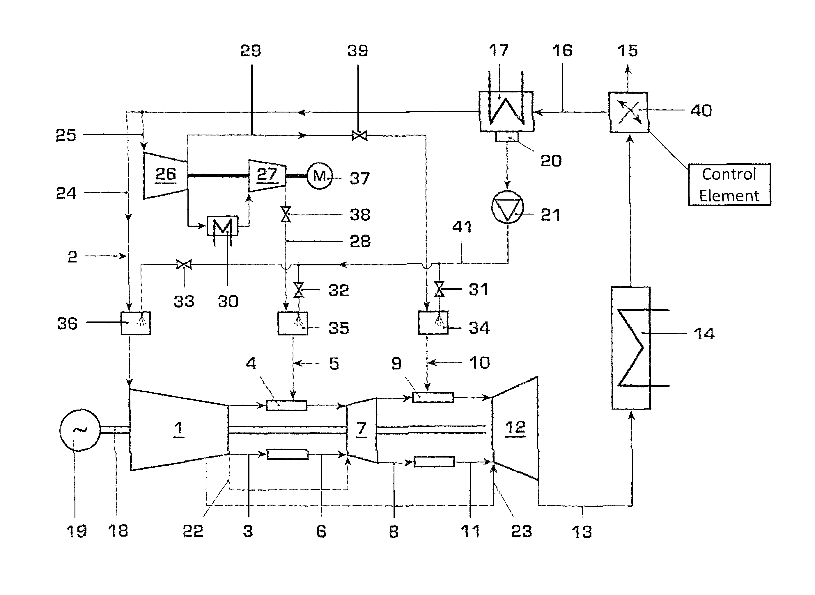
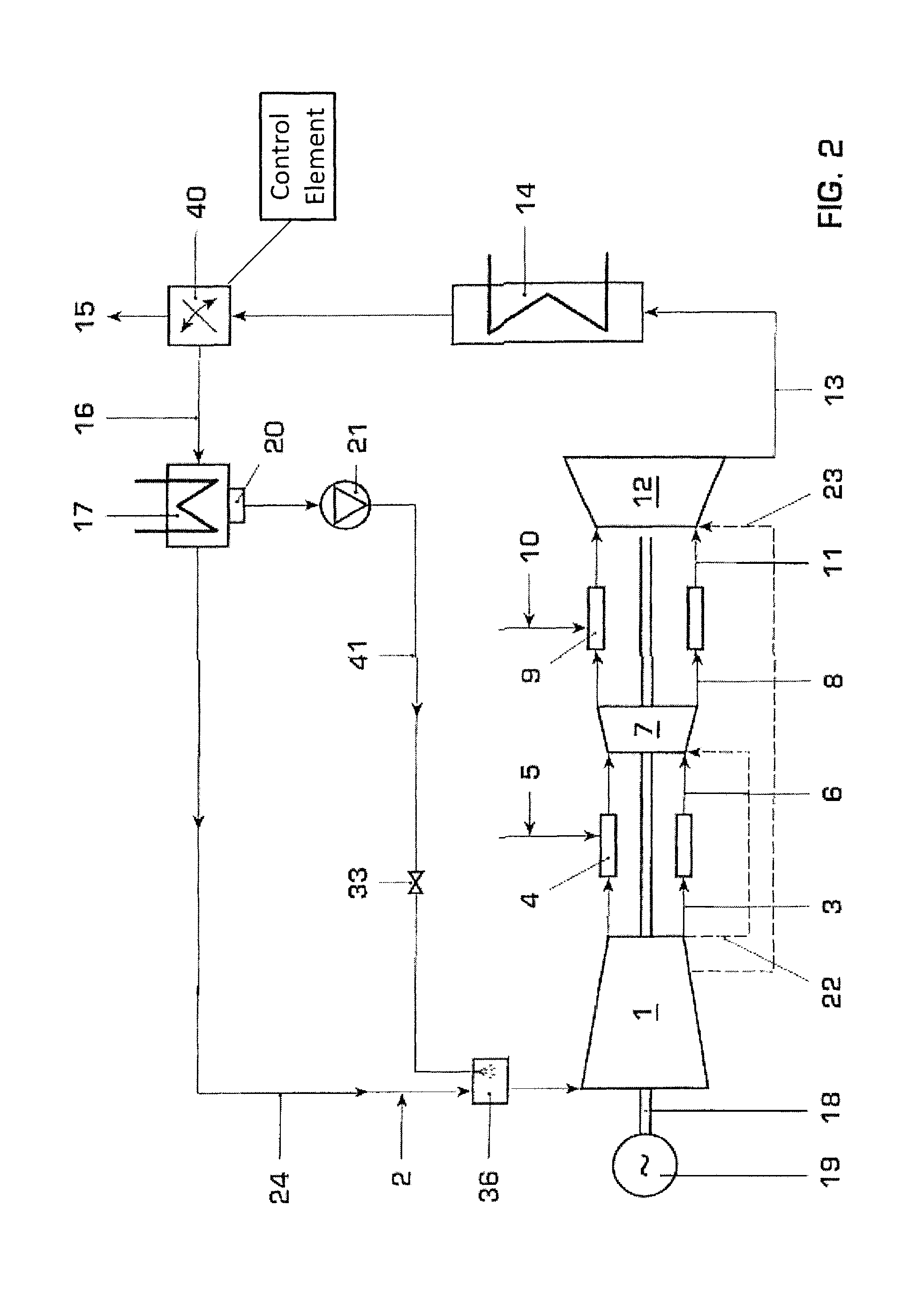
This patent text describes a method and installation for a gas turbine that can use hydrogen-rich fuel gas. The method involves cooling the flue gas and recirculating a portion of it back into the compressor's air intake. The amount of recirculated gas is controlled by a control element, and the control reference is either the residual oxygen content of the flue gas or the oxygen content of the combustion air. The gas turbine installation includes a compressor, combustion chamber, turbine, and a flow splitter in the flue gas passage, along with the necessary control elements and a device for recooling the recirculated flue gas flow. The technical effects of this patent text are improved efficiency and reduced emissions from the gas turbine, as well as improved performance and reliability.

Problems solved by technology

On the other hand, limited natural gas reserves have led to considerations of using synthetically processed gaseous fuels alternatively to, or in combination with, the combustion of conventional types of fuel.
The combustion of hydrogen in known combustion systems of gas turbines can lead to, for example, flashback and increased NOx emissions, on account of the high flame velocity and short ignition delay time of the hydrogen.

Method used


Image

  • Gas turbine installation with flue gas recirculation dependent on oxygen content of a gas flow
  • Gas turbine installation with flue gas recirculation dependent on oxygen content of a gas flow
  • Gas turbine installation with flue gas recirculation dependent on oxygen content of a gas flow

Examples


Embodiment Construction

[0020]An exemplary gas turbine installation is disclosed herein which can provide a reliable combustion with low CO and NOx emissions—which can be especially robust with regard to flashback—of hydrogen-rich fuel gases in gas turbines. Exemplary embodiments can address hydrogen-rich fuel gases with short ignition delay and high flame velocities, which can make a good premixing of air and fuel gas (which can be indispensable for low emissions) more difficult. Fuel gases with approximately 30% to 100% (e.g., ±10% or lesser or greater) of hydrogen portion are considered as hydrogen-rich fuel gases. These can, for example, be syngases or pure hydrogen.

[0021]An exemplary method is disclosed for the reduction of the oxygen content in combustion air of gas turbine installations via recirculation of flue gas.

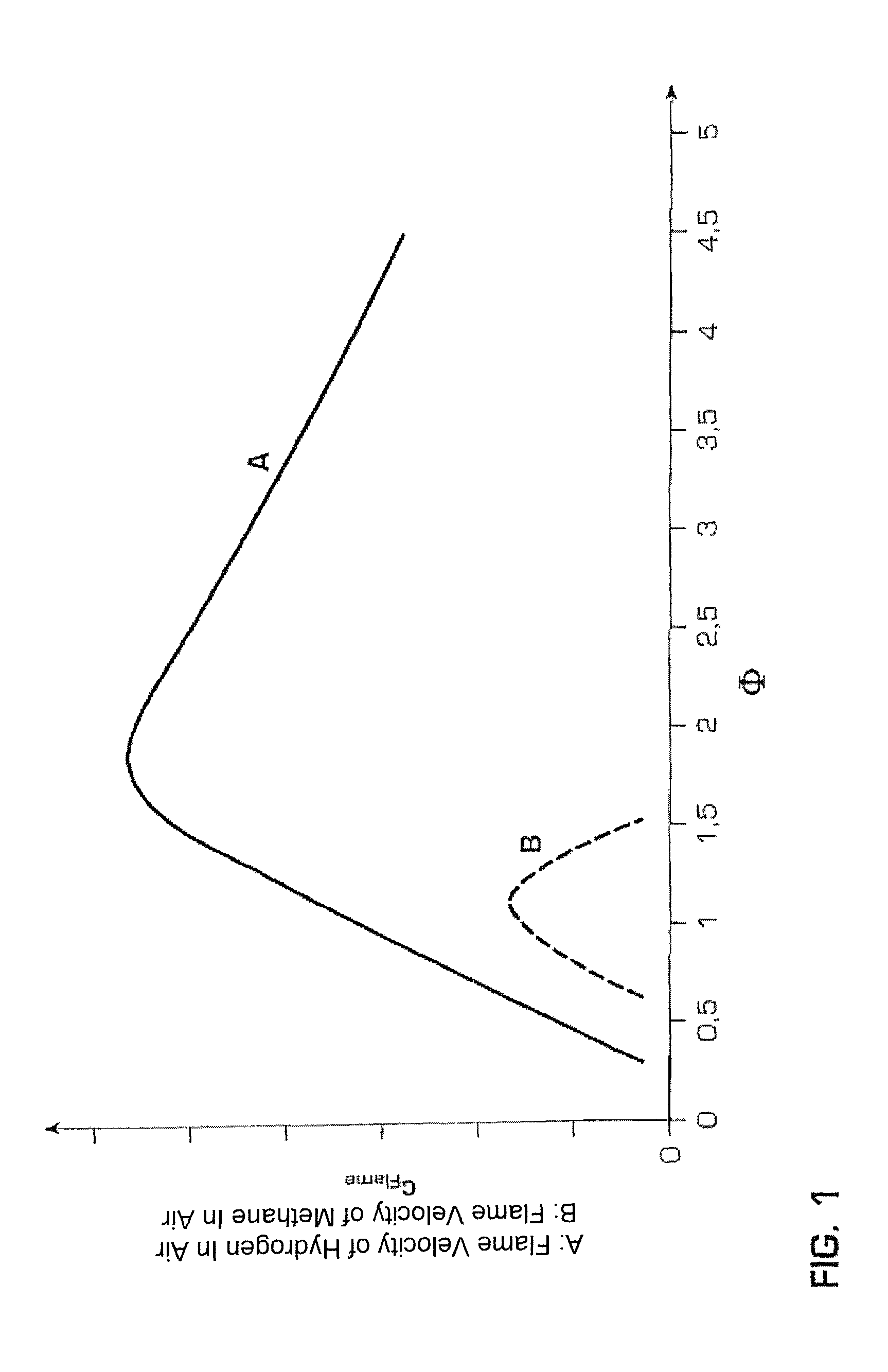
[0022]Hydrogen combustion can be understood with reference to FIG. 1 which shows the flame velocity of hydrogen in air (A) and methane in air (B) under atmospheric conditions in dependen...


PUM


Abstract

A method and installation are disclosed which can, for example, provide for reliable, low-Nox-emission operation of a gas turbine installation with hydrogen-rich fuel gas. An exemplary gas turbine installation includes an arrangement for flue gas recirculation into a compressor inlet and for fuel gas dilution. Oxygen content in combustion air can be reduced by recirculation of recooled flue gas, and the fuel gas can be diluted with compressed flue gas. The oxygen reduction in the combustion air can lead to minimum residual oxygen in the flue gas which can be used for fuel gas dilution. As a result of the flue gas recirculation, water content in the combustion air can be increased by feedback of the water which results as a combustion product. The oxygen reduction, increased water content, and fuel dilution can reduce the flame velocity of hydrogen-rich fuel gases and enable a robust, reliable and low-emission combustion.

Description

RELATED APPLICATIONS[0001]This application claims priority as a continuation application under 35 U.S.C. §120 to PCT / EP2008 / 057062, which was filed as an International Application on Jun. 6, 2008 designating the U.S., and which claims priority to Swiss Application 00982 / 07 filed in Switzerland on Jun. 19, 2007. The entire contents of these applications are hereby incorporated by reference in their entireties.FIELD[0002]The disclosure relates to a gas turbine installation and a method for operating a gas turbine installation, such as installation with hydrogen-rich fuel gas wherein oxygen content of the combustion air can be reduced via flue gas recirculation.BACKGROUND INFORMATION[0003]The research and development of the combustion of hydrogen or hydrogen-rich fuels in gas turbines involves at least two factors:[0004]On the one hand, there is a global interest in reducing the emission of greenhouse gases, especially of CO2. One possibility for this is the changeover from fossil fuel...

Claims


Application Information

Patent Timeline
Patent Type & Authority Patents(United States)
IPC IPC(8): F02C7/08
CPCF23C9/00F02C3/30F02C3/34F02C7/143F05D2270/08F23C6/042F23C2202/20F23C2900/9901F23J15/06Y02E20/18Y02E20/363Y02E20/30
Inventor BRAUTSCH, ANDREASWINKLER, DIETERCARRONI, RICHARD
Owner GENERAL ELECTRIC TECH GMBH
Learn More