Rotary electric machine

a rotary electric machine and rotary technology, applied in the direction of dynamo-electric machines, ac commutators, electrical devices, etc., can solve the problems of non-uniform winding, non-uniform coil ends, and hinder so as to improve the rationalization of manufacturing processes

Inactive Publication Date: 2014-08-05
MITSUBISHI ELECTRIC CORP
View PDF13 Cites 10 Cited by
  • Summary
  • Abstract
  • Description
  • Claims
  • Application Information

AI Technical Summary

Benefits of technology

[0009]The present invention aims to solve the above problems and an object of the present invention is to provide a rotary electric machine in which phase windings of a wye winding are configured into parallel circuits to make density of electric current that flows through phase windings of the wye winding and density of electric current that flows through phase windings of a delta winding approximately equal without changing cross-sectional area of the conductor wires, making temperature distribution in a stator winding uniform, improving rationalization of manufacturing processes, and also enabling cyclic current flows in parallel circuit portions of the wye winding to be suppressed.
[0011]According to the present invention, phase windings of first and second delta windings and first and second wye windings are configured using conductor wires that have an identical cross-sectional shape. Thus, coil ends can be bent and shaped into identical shapes, increasing uniformity of the coil ends. The coils can be shaped using a single tool, and are suitable for rationalization of manufacturing processes.
[0012]Because the phase windings of the first and second wye windings are configured by connecting two winding portions in parallel, density of electric current that flows through the phase windings of the first and second wye windings can be reduced. Thus, the density of the electric current that flows through the phase windings of the first and second wye windings can be brought closer to the density of the electric current that flows through the phase windings of the first and second delta windings, enabling the temperature distribution of the stator winding to be made uniform.

Problems solved by technology

Thus, one problem has been that the density of the electric current that flows through the phase windings of the wye winding and the density of the electric current that flows through the phase windings of the delta winding are different, and temperature distribution in the stator winding is nonuniform.
Thus, the rigidity of the two kinds of conductor wires is different, and one problem has been that differences arise in the bendability of the two when the coil ends are bent and shaped, making the coil ends nonuniform.
Another problem has been that it is necessary to shape the coils using dedicated tools for each of the two kinds of conductor wires, hindering rationalization of the manufacturing process.

Method used


Image

  • Rotary electric machine
  • Rotary electric machine
  • Rotary electric machine

Examples


embodiment 1

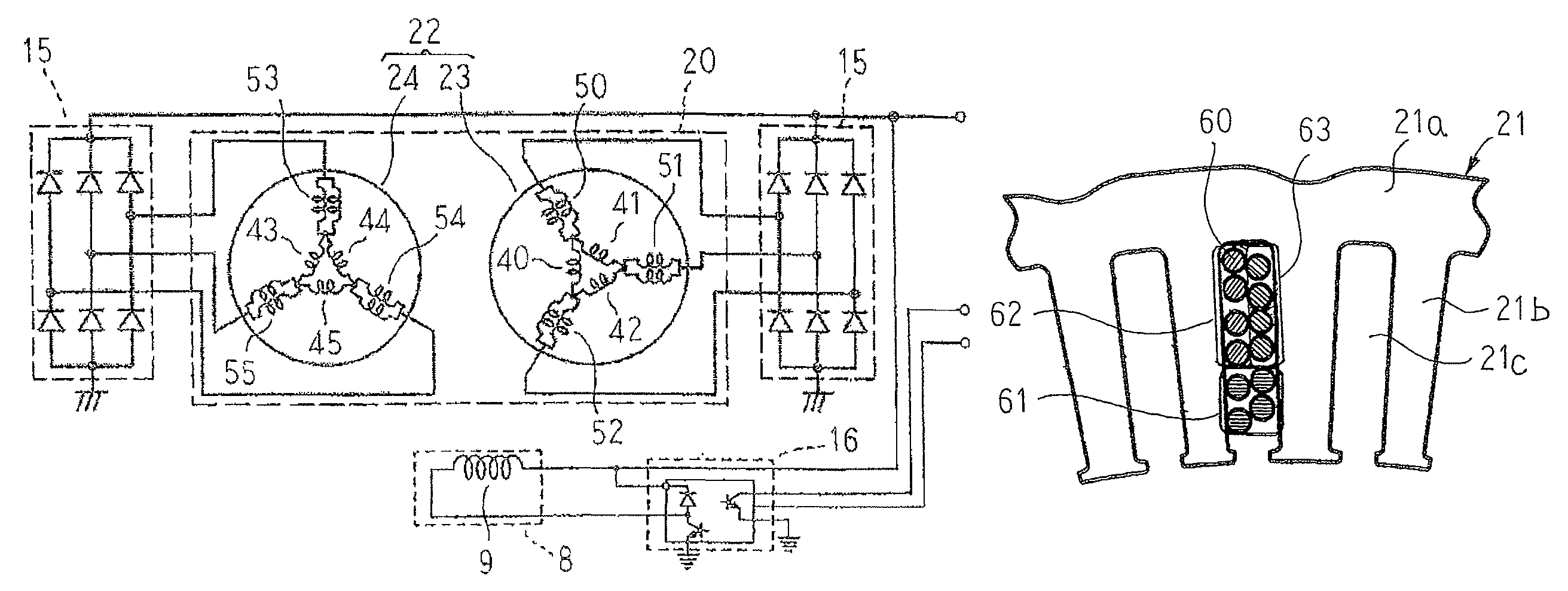
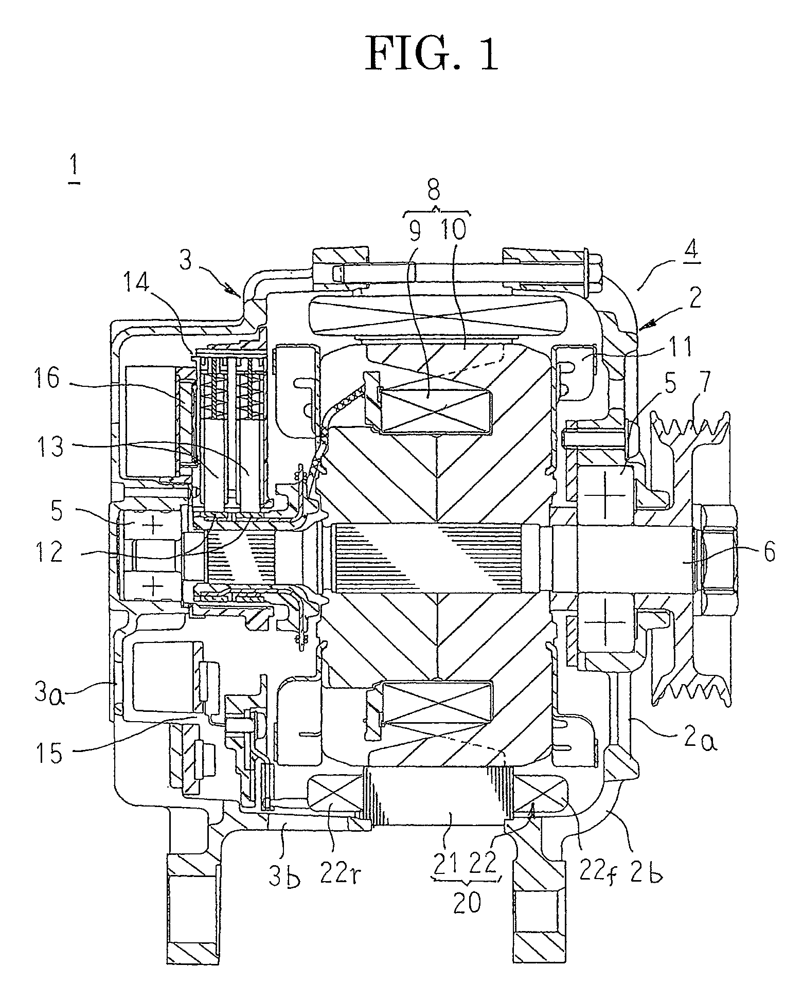
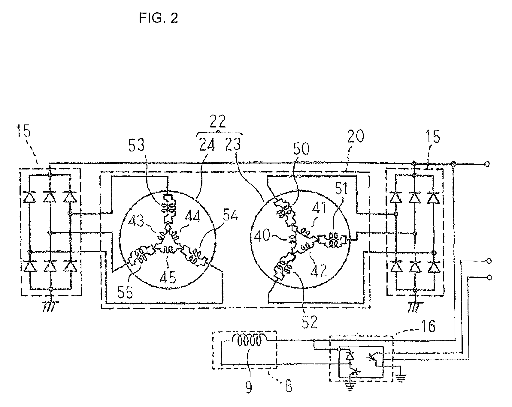
[0023]FIG. 1 is a longitudinal cross section that shows an automotive alternator according to Embodiment 1 of the present invention, and FIG. 2 is an electrical circuit diagram of the automotive alternator according to Embodiment 1 of the present invention.

[0024]In FIG. 1, an automotive alternator 1 that functions as a rotary electric machine includes: a housing 4 that is constituted by a front bracket 2 and a rear bracket 3 that are each approximately bowl-shaped and made of aluminum; a shaft 6 that is rotatably supported in the housing 4 by means of bearings 5; a pulley 7 that is fixed to an end portion of the shaft 6 that extends out frontward from the housing 4; a rotor 8 that is fixed to the shaft 6 and that is disposed inside the housing 4; a stator 20 that is fixed to the housing 4 so as to surround the rotor 8; a pair of slip rings 12 that are fixed to a rear end of the shaft 6, and that supply electric current to the rotor 8; a pair of brushes 13 that slide on respective su...

embodiment 2

[0071]FIG. 7 is a schematic diagram that shows a connected state of a first three-phase wye-delta hybrid winding in an automotive alternator according to Embodiment 2 of the present invention, and FIG. 8 is a perspective that shows a stator in the automotive alternator according to Embodiment 2 of the present invention. Moreover, in FIG. 8, to facilitate explanation, only a single connection portion between a phase winding that constitutes a first delta winding and a phase winding that constitutes a first wye winding is shown.

[0072]In FIGS. 7 and 8, an additional wire 38 is made of a copper wire that is coated with an insulator that is identical to the conductor wires 30, and is disposed so as to extend in a circumferential direction over the coil end groups 22r such that a first end thereof is joined by welding, etc., to end portions of two conductor wires 30 that constitute a connection portion between a delta-U1-phase winding 40 and a delta-V1-phase winding 41 and a second end th...


PUM


Abstract

The stator winding includes: a first three-phase wye-delta hybrid winding that is configured by connecting phase windings of a first wye winding to respective output ends of a first delta winding; and a second three-phase wye-delta hybrid winding that is configured by connecting phase windings of a second wye winding to respective output ends of a second delta winding. The phase windings of the first and second wye windings are configured by connecting two winding portions in parallel, and those two winding portions are configured such that distributions of radial positions inside slots of conductor wires that constitute the winding portions are equal.

Description

BACKGROUND OF THE INVENTION[0001]1. Field of the Invention[0002]The present invention relates to a rotary electric machine such as an automotive alternator, and particularly relates to a stator winding mounting construction for a stator core in which slots are formed at a ratio of two slots per phase per pole.[0003]2. Description of the Related Art[0004]In conventional rotary electric machines, a stator is formed so as to have a slot count at a ratio of two slots per phase per pole, and an armature winding is constituted by two three-phase wye-delta hybrid windings. Moreover, the three-phase wye-delta hybrid windings include: a delta winding in which three phase windings are delta-connected; and a wye winding that is constituted by three phase windings that are connected to respective output ends of the delta winding.[0005]However, in wye-delta hybrid windings, when only the fundamental wave is considered, an electric current that is √3 times the electric current that flows through ...

Claims


Application Information

Patent Timeline
Patent Type & Authority Patents(United States)
IPC IPC(8): H02K3/12H02K3/28
CPCH02K3/28H02K3/50
Inventor IMAZAWA, YOSHIROTANAKA, KAZUNORI
Owner MITSUBISHI ELECTRIC CORP
Why Eureka
Try Eureka