Radiographic apparatus

a technology of radiography and apparatus, applied in the field of radiography apparatus, can solve the problem of subject being exposed to a higher dose of radiation in the tomography mod

Active Publication Date: 2014-08-05
SHIMADZU CORP
View PDF8 Cites 152 Cited by
  • Summary
  • Abstract
  • Description
  • Claims
  • Application Information

AI Technical Summary

Benefits of technology

[0030]The radiographic apparatus according to this invention may select the spot radiography mode or the tomography mode. Moreover, the radiation detecting device provided in the radiographic apparatus according to this invention converts radiation into an electric signal, and thereafter amplifies the signal to output it to the image generation device. According to this invention, an amplification factor is higher in the tomography mode than that in the spot radiography mode. The tomographic image is obtained through superimposing two or more fluoroscopic images. In comparison of the fluoroscopic images, they differ from one another in appearance of the false image. Accordingly, superimposing the images may achieve cancel of the false image. In this way, a tomographic image finally obtained has no false image. Since the spot radiography is conducted by a low amplification factor as usual, the fluoroscopic image in the spot radiography is clear with no false image appearing therein.

Problems solved by technology

The conventional configuration, however, has the following problem.
That is, the conventional configuration has a problem that the subject is exposed to a higher dose of radiation in the tomography mode.

Method used


Image

  • Radiographic apparatus
  • Radiographic apparatus
  • Radiographic apparatus

Examples


embodiment 1

[0050]Each embodiment of radiographic apparatus according to Embodiment 1 will be described hereinafter with reference to the drawings. Herein, X-rays in each embodiment correspond to radiation in Embodiment 1.

[0051]

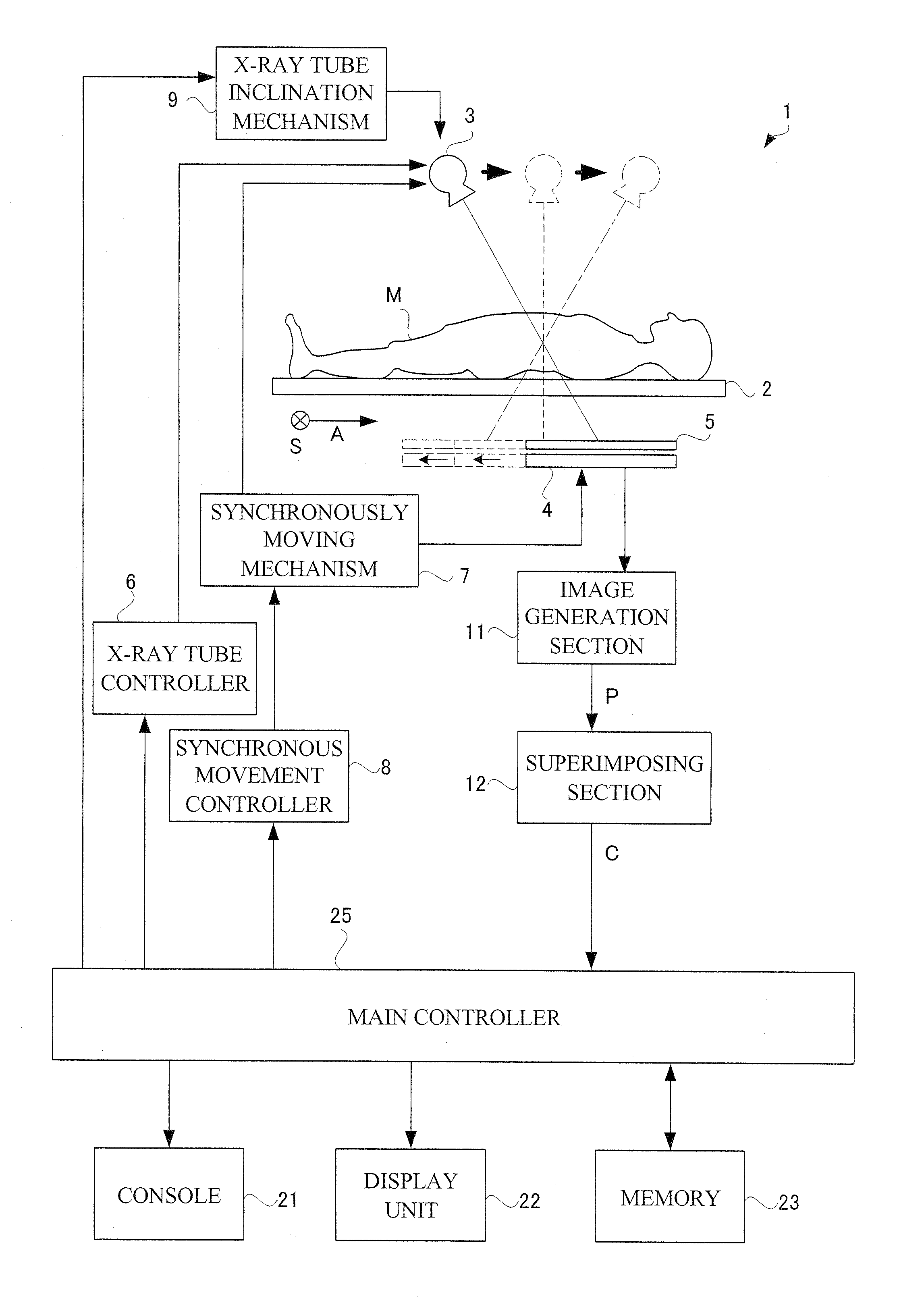
[0052]FIG. 1 is a functional block diagram showing a configuration of radiographic apparatus according to Embodiment 1. As shown in FIG. 1, an X-ray apparatus 1 in Embodiment 1 includes a top board 2 for supporting a subject M as a target for X-ray tomography, an X-ray tube 3 disposed above the top board 2 for irradiating the subject with X-ray beams in a cone shape, a flat panel detector (hereinafter, abbreviated as FPD) 4 disposed below the top board 2 for detecting X-rays transmitting through the subject M, a synchronously moving mechanism 7 and a synchronous movement controller 8 for controlling thereof, the synchronously moving mechanism 7 moving the X-ray tube 3 and the FPD 4 synchronously in opposite directions to each other across a site of interest of the subjec...

embodiment 2

[0075]Next, X-ray apparatus 30 according to Embodiment 2 will be described. FIG. 8 is a functional block diagram of tomographic X-ray apparatus according to Embodiment 2. As shown in FIG. 8, the X-ray apparatus according to Embodiment 2 is similar to the configuration described in Embodiment 1. Therefore, description of like components will be omitted as appropriate. The configuration of Embodiment 2 is different from that of Embodiment 1 in the mode of movement of the X-ray tube 3 and FPD 4 and the mode of image processing of X-ray fluoroscopic images. The FPD 4 has the same configuration as that in Embodiment 1, and thus description thereof is to be omitted.

[0076]The synchronously moving mechanism 7 moves the FPD 4 disposed below the top board 2 straight along the direction of the body axis A of a subject M synchronously with straight movement of the X-ray tube 3 described above. The FPD 4 has the same moving direction as the X-ray tube 3. That is, the cone-shaped X-ray beam with ...


PUM


Abstract

One object of this invention is to provide radiography apparatus with suppressed exposure to a subject in tomography mode. An FPD provided in X-ray apparatus according to this invention converts X-rays into electric signals, and thereafter amplifies the signals to output them to an image generation section. According to this invention, an amplification factor is higher in a tomography mode than in a spot radiography mode. A tomographic image is obtained through superimposing two or more fluoroscopic image. In comparison of the fluoroscopic images, they differ from one another in appearance of the false image. Accordingly, superimposing the images may achieve cancel of the false images. In this way, the tomographic image finally obtained has no false image.

Description

TECHNICAL FIELD[0001]This invention relates to radiographic apparatus provided with a radiation source and an FPD. In particular, this invention relates to radiographic apparatus that allows selection of any one of a tomography mode and a spot radiography mode. In the tomography mode, a series of fluoroscopic images are taken while the radiation source and the FPD moves synchronously in opposite directions to each other, and the images are superimposed to obtain a sectional image of a subject. In the spot radiography mode, a single fluoroscopic image is taken through irradiating with single shot radiation.BACKGROUND ART[0002]Medical institutions are equipped with radiographic apparatus 51 for obtaining a tomographic image of a subject M. Such radiographic apparatus 51 includes a configuration in which a radiation source 53 that emits radiation and an FPD 54 that detects radiation move synchronously to continuously take a series of fluoroscopic images, and then the series of fluorosc...

Claims


Application Information

Patent Timeline
Patent Type & Authority Patents(United States)
IPC IPC(8): A61B6/00
CPCA61B6/5258A61B6/025A61B6/4233A61B6/4441A61B6/4452A61B6/542
Inventor NOTOHARA, DAISUKESHIBATA, KOICHI
Owner SHIMADZU CORP
Why Eureka
Try Eureka