
Tension monitoring apparatus

a technology of tension monitoring and monitoring apparatus, which is applied in the direction of apparatus for force/torque/work measurement, screws, instruments, etc., can solve the problems that the system is not immune to a dangerous collapse, and the tension must be removed

Inactive Publication Date: 2014-08-12
TOMCAT USA
View PDF8 Cites 1 Cited by
  • Summary
  • Abstract
  • Description
  • Claims
  • Application Information

AI Technical Summary

Benefits of technology

The invention is about a device that can continuously monitor the tension on cables and rods used for staging and lighting platform trusses, support systems and structures. This device allows for easy assembly and disassembly of temporary platforms and staging used for performances and special events. It is made of aluminum or steel and permanently installed between a connection or anchor point and the guy cable line or structural rod. This device helps to increase confidence that the tension on the rods and cables is correct.

Problems solved by technology

These systems, however, are not immune to a dangerous collapse as was experienced a few years ago at the Indiana State Fair.
Although the instructions and engineering reports that are provided with the lighting and or staging platforms and systems require that all guy cables and structural rods should be pre-tensioned to a set value depending on the requirements for each location, one of the more difficult issues that must be handled, is how to properly set the pre-tension, and perhaps even more importantly is how to be sure that the pretension is maintained once properly set.
A major problem with this technique is that once the tension is set, the tension must be removed before the measuring device can be removed.

Method used


Image

  • Tension monitoring apparatus
  • Tension monitoring apparatus
  • Tension monitoring apparatus

Examples


Embodiment Construction

[0021]The making and using of the presently preferred embodiments are discussed in detail below. It should be appreciated, however, that the present invention provides many applicable inventive concepts that can be embodied in a wide variety of specific contexts. The specific embodiments discussed are merely illustrative of specific ways to make and use the invention, and do not limit the scope of the invention.

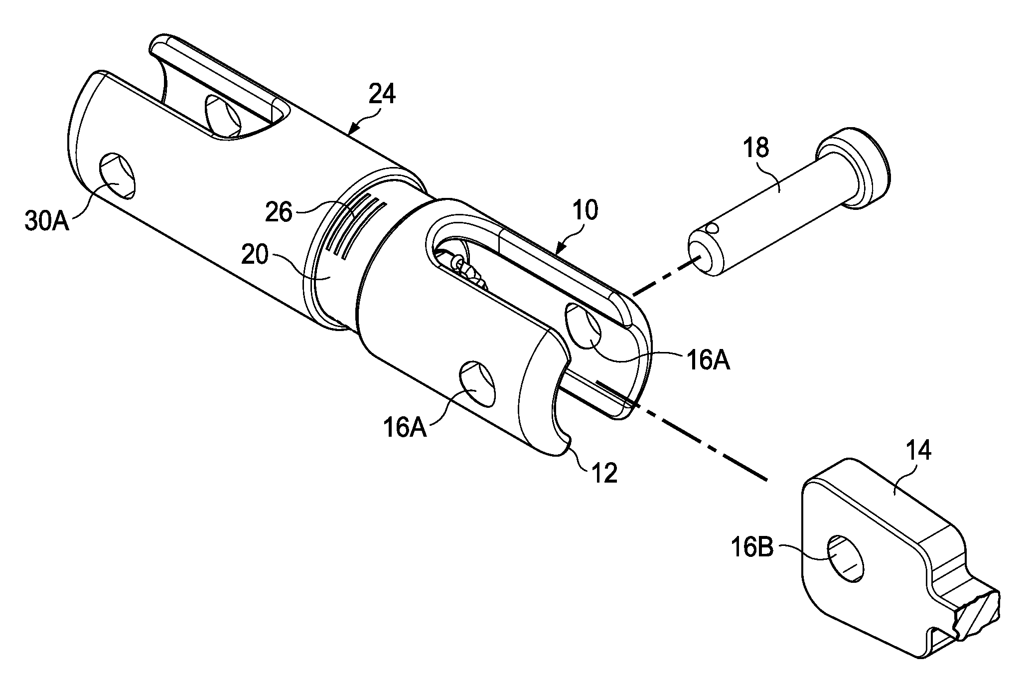
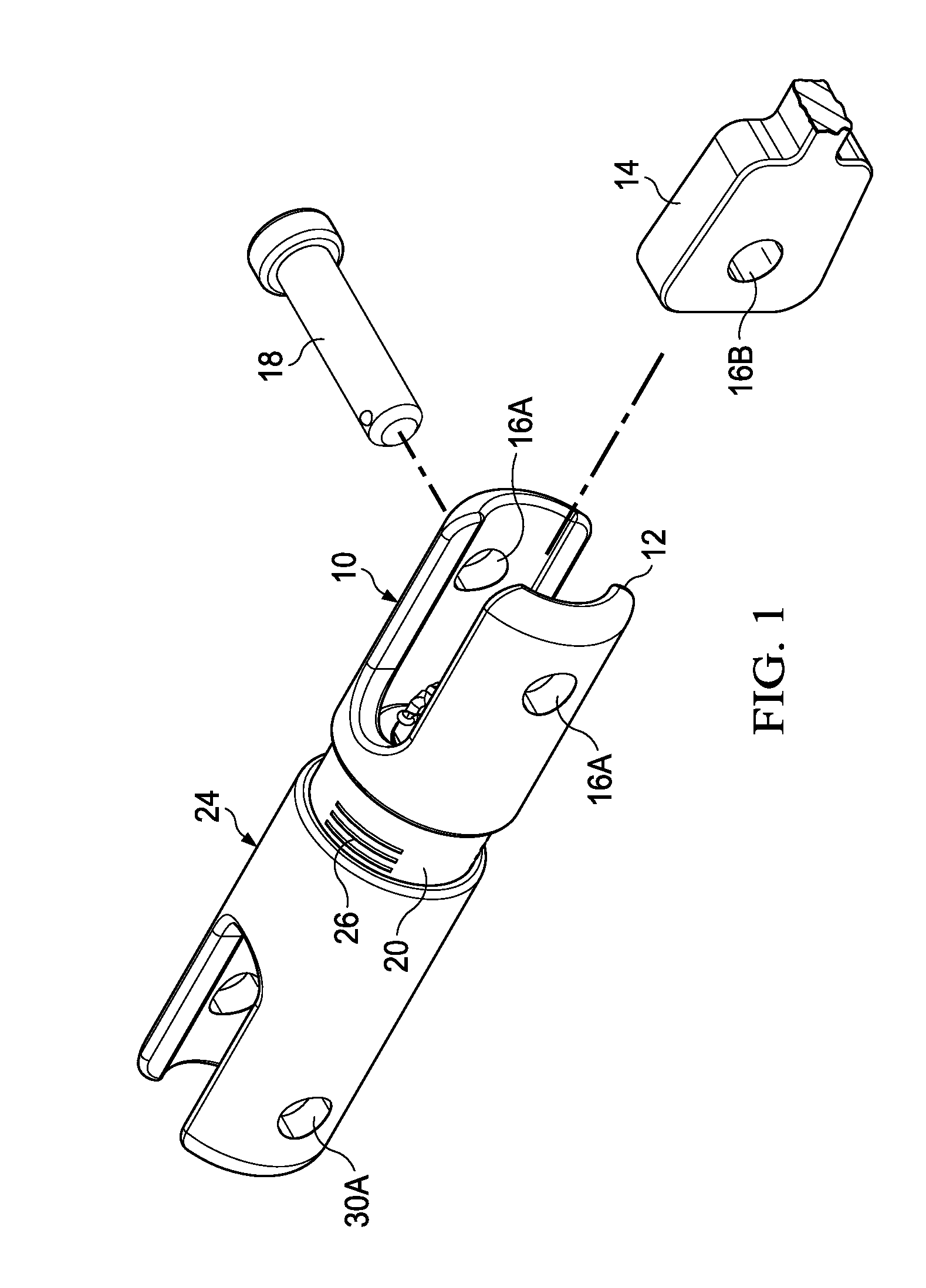
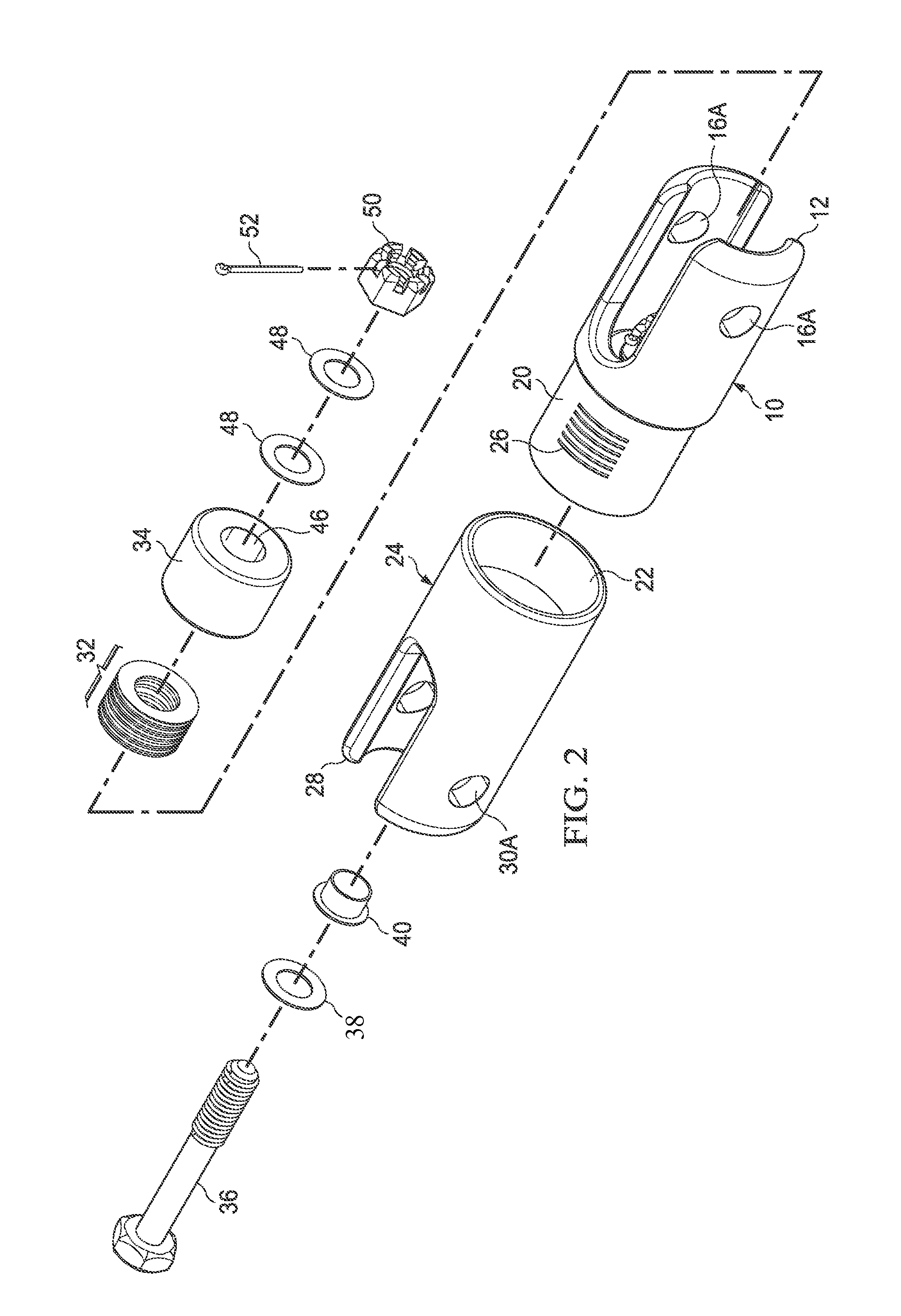
[0022]FIGS. 1 and 2 show an assembled view and an exploded view of one embodiment of the tension monitoring device of the present invention. As shown in FIG. 1, the device includes a first member 10 having a “clevis” first end 12 for attaching to a first connecting point or structure such as a “spade” type device 14 that is in turn is connected to a cable or structural rod that will be in tension. As shown end 12 defines an aperture 16A, and the spade device 14 defines a similar aperture 16B such that when spade 14 is moved in to the clevis end 12, the clevis and the spade ca...


PUM


Abstract

A tension monitoring assembly or device permanently installed between a connection or anchor point and a guy cable line or structural rod allows constant monitoring and increase confidence that the guy cable or structural tension rod remains tensioned to the proper value. The device includes a plurality of compression members and a connecting member that are arranged between connection points such that the tension between a first connecting point and a second connection point may be set to a selected value. The tension on the device is determined by the distance between two members of the device such that a change in the tension from a set amount will result in a change of the distance between the two members. This change in distance can be determined by indicia that are visible as the two members move with respect to each other.

Description

TECHNICAL FIELD[0001]This invention relates generally to a tension monitoring apparatus.BACKGROUND[0002]Temporary roof systems have been used in the entertainment business for many years. These systems, however, are not immune to a dangerous collapse as was experienced a few years ago at the Indiana State Fair. These prior art temporary roof systems are typically anchored to the ground with a series of guy cables that run from the in place roof position to an anchor / ballast point. Although the instructions and engineering reports that are provided with the lighting and or staging platforms and systems require that all guy cables and structural rods should be pre-tensioned to a set value depending on the requirements for each location, one of the more difficult issues that must be handled, is how to properly set the pre-tension, and perhaps even more importantly is how to be sure that the pretension is maintained once properly set. Most techniques for setting the pretension use elect...

Claims


Application Information

Patent Timeline
Patent Type & Authority Patents(United States)
IPC IPC(8): F16B31/02
CPCG01L5/103B60P7/0861G01N3/08G01L5/06
Inventor TODD, IV, HARRY, WILLIAM
Owner TOMCAT USA
Learn More