Oil cavity for pendulum element (roller) of a centrifugal pendulum

a centrifugal pendulum and pendulum element technology, which is applied in the direction of shock absorbers, mechanical devices, inertia effect dampers, etc., can solve the problems of reducing the absorption effect, affecting the entire vibration behavior of the motor vehicle, and damage to the centrifugal pendulum. , to achieve the effect of improving the vibration behavior

Inactive Publication Date: 2014-08-12
SCHAEFFLER TECH AG & CO KG
View PDF14 Cites 8 Cited by
  • Summary
  • Abstract
  • Description
  • Claims
  • Application Information

AI Technical Summary

Benefits of technology

[0006]The object is met by means of a centrifugal pendulum, for example, in a torsional vibration damper of a drive train of a motor vehicle with a pendulum flange rotating about a rotation axis and several restrictedly displaceable pendulum masses distributed over the circumference, limited relative to the pendulum flange within limit stops, wherein the limit stops of the pendulum masses are hydraulically dampened on the pendulum flange. Through the hydraulic dampening, hard impact of the pendulum masses is avoided. In the sense of the invention, before hard metallic impact on the pendulum flange or on the interposed components, the pendulum masses run onto an interposed buffer comprising hydraulic fluid that can be displaced with an increasing impact pressure.
[0007]In a particularly advantageous manner, hydraulic damping can be provided in arrangements in which the pendulum masses are accommodated by means of elements that roll in races formed by cutouts in both the pendulum flange and pendulum masses. Generally, in this case, the swivel paths are demarcated by limit stops of the cutouts on which the rolling elements run onto during traverse of pendulum masses relative to the pendulum flange. In the process, the rolling elements can run on the corresponding limit stops in the circumferential direction on both sides of the cut outs in the pendulum flange as well as in the pendulum masses. It is therefore proposed for such exemplary embodiments, in the section of at least a limit stop, however, preferably on all limit stops in connection with the associated rolling element, to form a chamber with a gap that is at least partially filled with hydraulic fluid, so that when a rolling element approaches the limit stop, the chamber is formed and upon further approach of the rolling element to the limit stop, the hydraulic fluid trapped inside the chamber is squeezed out through the gap formed between the rolling element and the cutout. In this manner, resistance develops over the remaining traverse up to the hard impact, which prevents hard impact of the pendulum mass against the pendulum flange or if applicable prevents an impact entirely.
[0009]To further seal the preferably disc-shaped components, at least partially on their sides, namely pendulum flange and pendulum masses, and hence prevent the leakage of hydraulic fluid without resistance, a chamber provided in the cutout of the pendulum flange can at least be closed partially on the face sides of the pendulum flanges, by means of a ring board disposed respectively on the rolling element. For instance, two axially displaced ring boards of a barrel-shaped rolling element slides along the side surfaces of the pendulum flanges, whereby they are radially extended such that they flatly cover the rolling elements when approaching the rolling element on the chamber. The ring board, at the same time, can serve for axial stabilization of the rolling element in the cutout.
[0010]In the same manner, the ring board, at least partially, can close a chamber provided in the cutout of a pendulum mass, on the side of the pendulum mass facing the pendulum flange, whereas the side of the pendulum mass facing away from the pendulum flange can be closed preferably by shutter at least partially. In the process, the distances of ring collars from the side surfaces of pendulum masses or rather of the pendulum flange and / or the shutter likewise feature clearance from the side surfaces, so that, under pressure, hydraulic fluid can escape from this point.

Problems solved by technology

This can reduce the absorption effect of the centrifugal pendulum or even lead to a resonance, so that the deterioration of insulation behavior of the centrifugal pendulum can worsen the entire vibration behavior of the motor vehicle.
Moreover, the centrifugal pendulum can be damaged.

Method used


Image

  • Oil cavity for pendulum element (roller) of a centrifugal pendulum
  • Oil cavity for pendulum element (roller) of a centrifugal pendulum

Examples


Embodiment Construction

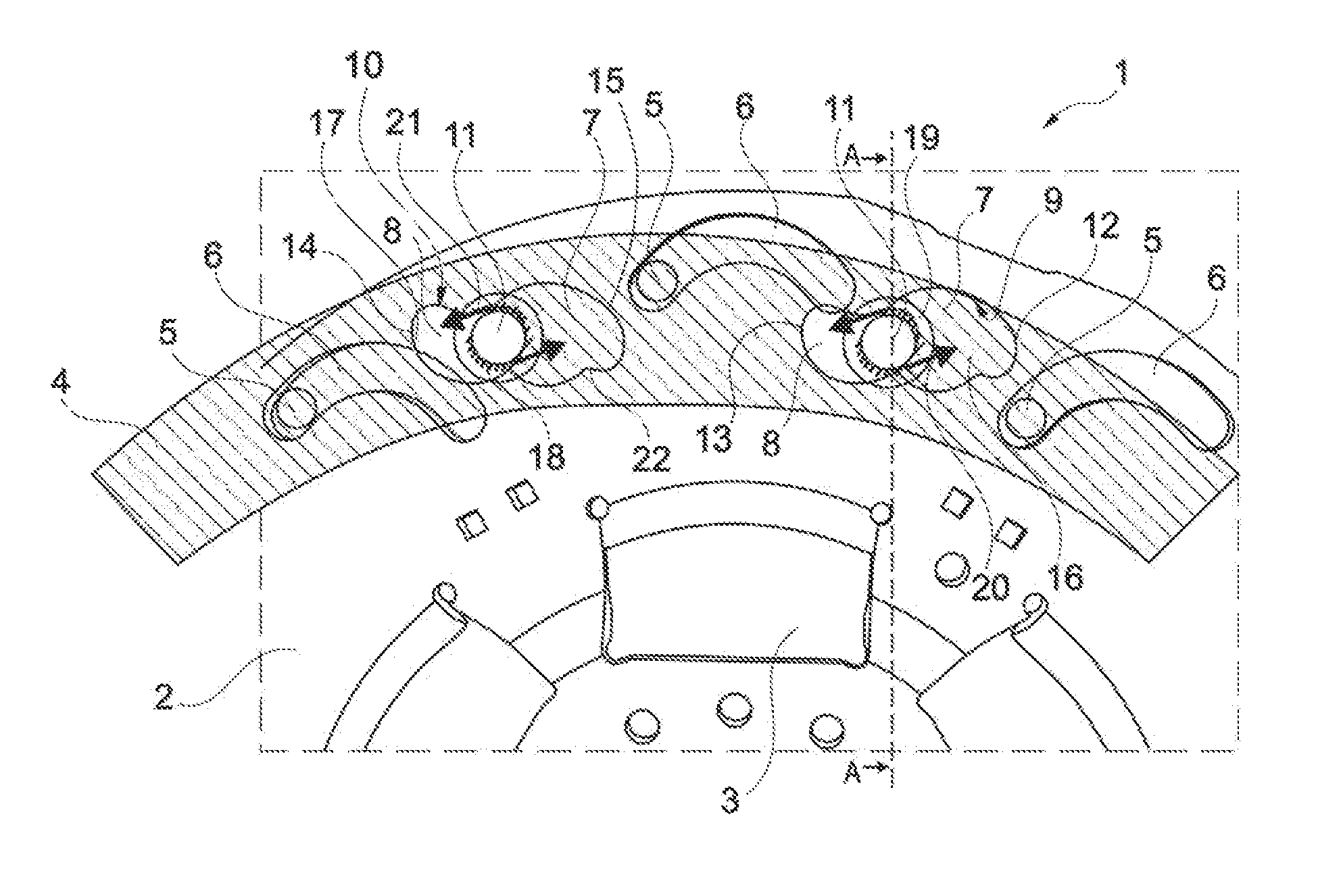
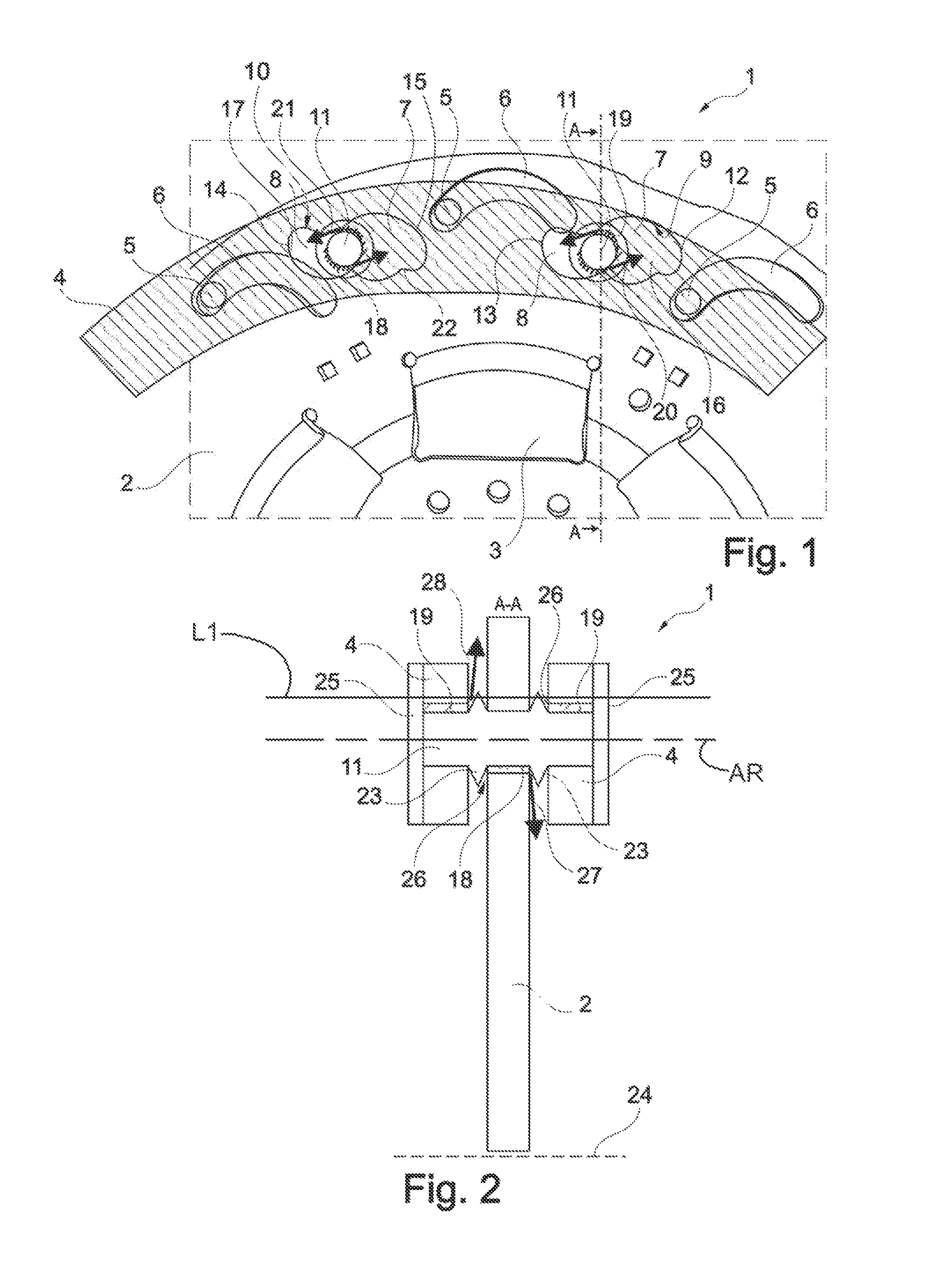
[0017]FIG. 1 shows a section of a centrifugal pendulum 1. The basic structure of centrifugal pendulum and torsional vibration dampers, for instance, can be derived from DE 10 2006 028 556 A1. The centrifugal pendulum 1 is formed out of the pendulum flange 2, which as a functional component of a torsional vibration damper contains window-shaped cutouts 3 for receiving or pressurizing energy accumulators acting in circumferential direction and can serve as the disc part for a torsional vibration damper.

[0018]Radially outside the cutouts 3 are pendulum masses 4 distributed over the circumference in a manner capable of swinging, and said masses 4 are accommodated on the pendulum flange 2, one on either side of the pendulum flange 2, and are connected rigidly with one another by means of a connection means 5 like bolts or rivets. The pendulum flange 2 is provided with through-punches 6, through which the connection means are guided and their form corresponds to the swing range of the pen...


PUM


Abstract

A centrifugal pendulum in a torsional vibration damper of a drive train of a motor vehicle with a pendulum flange rotating about a rotation axis and several pendulum masses distributed over the circumference, disposed on the latter in a manner capable of swinging. When the internal combustion engine of the drive train induces massive rotational irregularities resulting from high vibration angles in these arrangements, the pendulum masses can be deflected more strongly relative to the pendulum flange and strike the provided swing motion limits. To prevent hard hits of the pendulum masses on the pendulum flanges, it is proposed to dampen the impact areas by hydraulic means and hence to achieve a soft impact.

Description

CROSS-REFERENCE TO RELATED APPLICATIONS[0001]This application claims priority from German Patent Application No. DE 10 2009 007 830.4, filed Feb. 9, 2009 which application is incorporated herein by reference in its entirety.FIELD OF THE INVENTION[0002]The invention relates to a centrifugal pendulum, particularly in a torsional vibration damper of a motor vehicle drive train.BACKGROUND OF THE INVENTION[0003]Centrifugal pendulums are known, for instance, from German application documents published prior to examination DE 10 2006 028 556 A1 and DE 10 2007 024 115 A1. In this case, for instance, a pendulum flange that can be a component of a torsional vibration damper and can feature corresponding function elements such as window cutouts for energy accumulators, can be provided with cutouts on whose races rolling elements roll, which again roll in cutouts with races on pendulum masses, which are preferably disposed on both sides of side surfaces of the pendulum flange, whereby two oppos...

Claims


Application Information

Patent Timeline
Patent Type & Authority Patents(United States)
IPC IPC(8): F16D57/00F16F15/14
CPCF16F15/145Y10T74/2128
Inventor ENGELMANN, DOMINIQUEWERNER, MARKUS
Owner SCHAEFFLER TECH AG & CO KG
Why Eureka
Try Eureka