
Display device, electronic apparatus and lighting device

a technology of electronic equipment and lighting devices, applied in lighting and heating equipment, planar/plate-like light guides, instruments, etc., can solve the problems of uneven distribution of light introduced through the light-receiving surface of the light guide plate, inability to achieve the uniform luminance expected from a flat-surface (plate-shaped) lighting device, and deterioration of image quality. , to achieve the effect of suppressing the degradation of display quality

Active Publication Date: 2014-08-12
138 EAST LCD ADVANCEMENTS LTD
View PDF8 Cites 52 Cited by
  • Summary
  • Abstract
  • Description
  • Claims
  • Application Information

AI Technical Summary

Benefits of technology

This invention is about a display screen that is designed to have better quality lighting. The display screen has a structure that positions a light source substrate with multiple light emitting elements on one side. This structure is not exposed on the screen, which helps to maintain the quality of the display. The light emitting elements are aligned in a regular pattern to create even distribution of light intensity. Additionally, the light source substrate can be formed in a way that makes assembly easier or can be divided between adjacent blocks. Overall, this invention improves the quality and performance of display screens.

Problems solved by technology

This leads to a drawback in that the luminance of the illuminating light becomes uneven, resulting in remarkable degradation of image quality.
Accordingly, diffusion and reflection of the light become discontinuous and / or uneven and hence the light introduced through the light-receiving surface of the light guide plate is unevenly distributed.
Consequently, uniform luminance expected from a flat-surface (plate-shaped) lighting device is unable to be achieved, and the image quality is remarkably degraded.
However, since the positioning structure is located between the adjacent blocks, although the intensity of the illuminating light becomes partially discontinuous owing to the presence of the positioning structure, such a discontinuous portion is barely noticeable because the discontinuous portion is located between the regions with respect to which the illuminating light intensity is respectively controlled.

Method used


Image

  • Display device, electronic apparatus and lighting device
  • Display device, electronic apparatus and lighting device
  • Display device, electronic apparatus and lighting device

Examples


first embodiment

General Configuration

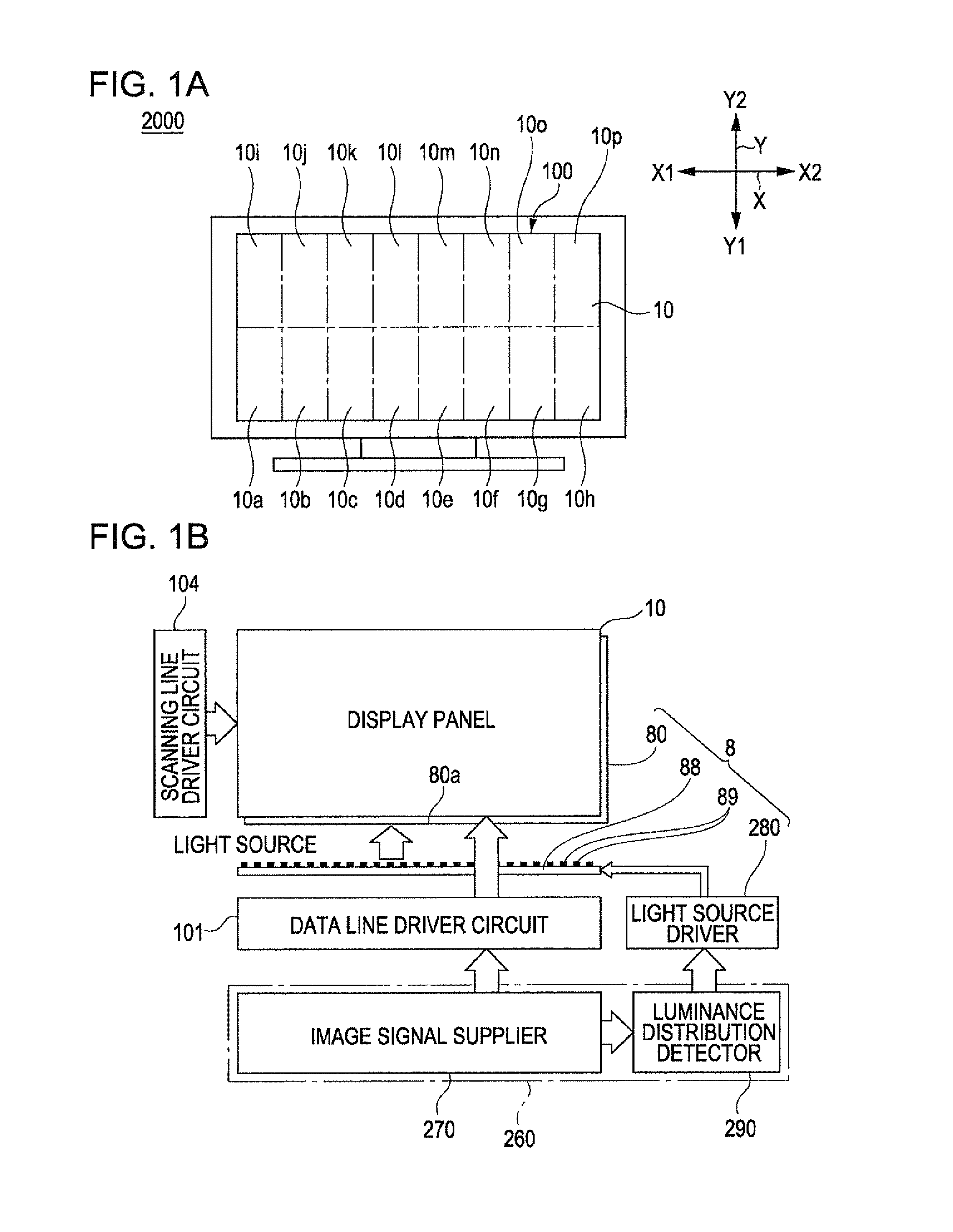
[0032]FIG. 1A is a schematic front view of a liquid crystal TV, exemplifying the electronic apparatus of the invention, including a display device according to a first embodiment, and FIG. 1B is a block diagram showing an electrical configuration of the display device.

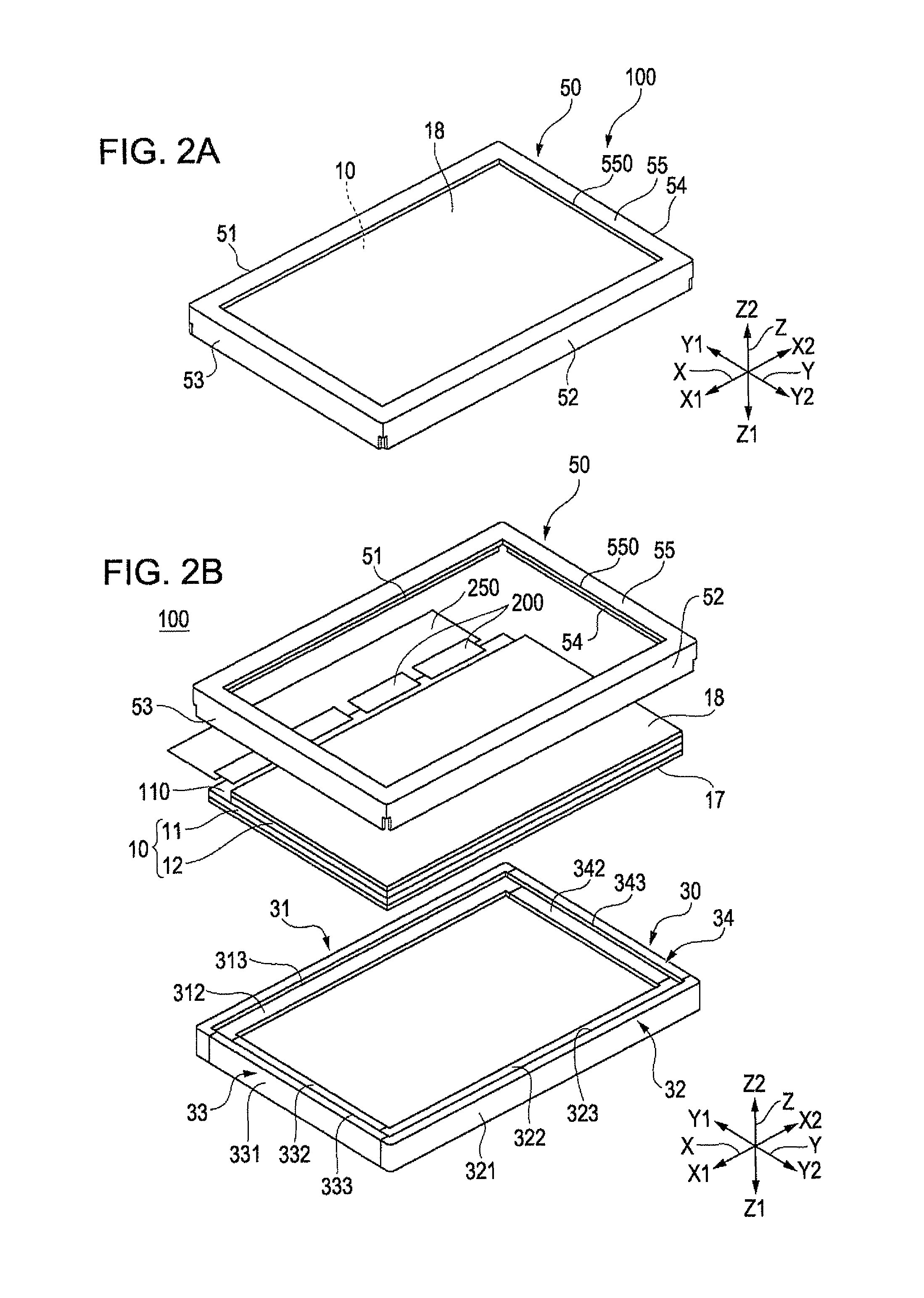
[0033]The electronic apparatus 2000 shown in FIG. 1A is a liquid crystal TV, and the display device 100 incorporated in the liquid crystal TV includes a transmissive display panel 10. As shown in FIG. 1B, the display device 100 includes, in addition to the display panel 10 to be subsequently described referring to FIG. 2A and other related drawings, an image signal supplier 270 that supplies image signals to the display panel 10 from outside through a flexible interconnect substrate, and a lighting device 8 disposed to overlap the rear face of the display panel 10 so as to supply illuminating light. The display device 100 includes a scanning line driver circuit 104 that drives scanning lines extend...

second embodiment

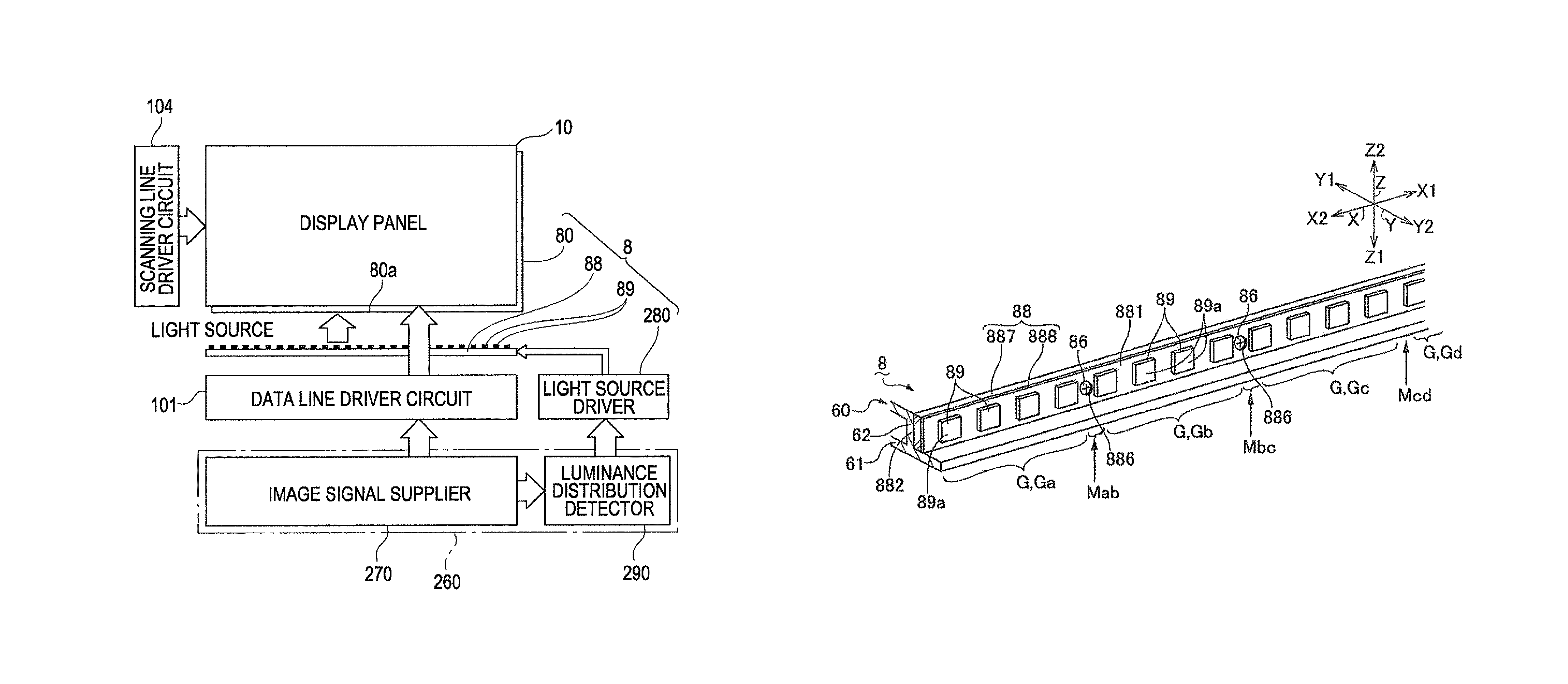
[0060]FIG. 6 is a perspective view showing a configuration of the light emitting elements 89 and the light source substrate 88 employed in the lighting device 8 of the display device 100, according to a second embodiment of the invention. The basic configuration of this embodiment is similar to that of the first embodiment, and therefore the same constituents will be given the same numeral and the description thereof will not be repeated.

[0061]In this embodiment also, as shown in FIG. 6, the plurality of light emitting elements 89 are mounted on the first surface 881 of the light source substrate 88 in the longitudinal direction thereof, as in the first embodiment. In addition, to perform the local dimming with the lighting device 8, the light emitting elements 89 are also divided into a plurality of unit blocks G (blocks Ga, Gb, Gc, . . . ) each including a predetermined number of light emitting elements located adjacent to each other in the longitudinal direction of the light sour...

third embodiment

[0064]FIG. 7 is a perspective view showing a configuration of the light emitting elements 89 and the light source substrate 88 employed in the lighting device 8 of the display device 100, according to a third embodiment of the invention. The basic configuration of this embodiment is similar to that of the first and the second embodiment, and therefore the same constituents will be given the same numeral and the description thereof will not be repeated.

[0065]In this embodiment also, as shown in FIG. 7, the plurality of light emitting elements 89 are mounted on the first surface 881 of the light source substrate 88 in the longitudinal direction thereof, as in the first and the second embodiment. In addition, to perform the local dimming with the lighting device 8, the light emitting elements 89 are also divided into a plurality of unit blocks G (blocks Ga, Gb, Gc, . . . ) each including a predetermined number of light emitting elements located adjacent to each other, in the longitudin...


PUM


Abstract

In a lighting device of a display device, a plurality of light emitting elements are mounted on a surface of a light source substrate, and the light source substrate is supported by a light source support member by means of a positioning (fixing) structure such as a metal screw. The plurality of light emitting elements are divided into a plurality of blocks, and the emission light amount can be controlled with respect to each of the blocks. Although the head of the screw is exposed on the surface of the light source substrate, the screw is located between adjacent ones of the blocks. Therefore, even though the illuminating light intensity becomes partially discontinuous owing to the presence of the screw, degradation of display quality originating from such discontinuity can be suppressed.

Description

BACKGROUND[0001]1. Technical Field[0002]The present invention relates to a display device that includes a lighting device and a display panel, an electronic apparatus that includes the display device, and the lighting device.[0003]2. Related Art[0004]A liquid crystal device, which is an example of existing display devices, includes a lighting device called a backlight device and a transmissive or semi-transmissive display panel (liquid crystal panel) disposed to overlap a light-emitting surface of the lighting device. The lighting device includes a light guide plate and a plurality of light emitting elements aligned so as to oppose one of the sides of the light guide plate that serves as a light-receiving surface, for example as disclosed in JP-A-2009-3081.[0005]In many of the thus-configured lighting devices, for example as shown in FIGS. 10A and 10B, light emitting elements 89 are mounted on a surface 881 of a light source substrate 88, and the light source substrate 88 is fixed w...

Claims


Application Information

Patent Timeline
Patent Type & Authority Patents(United States)
IPC IPC(8): G02B6/00
CPCG02F1/133615G02B6/0073G02B6/0068G02B6/009G02B6/0011G02F2001/133601G02F1/133601G02B6/0091
Inventor URANO, NOBUTAKAMOMOSE, YOICHI
Owner 138 EAST LCD ADVANCEMENTS LTD
Learn More