Grain conveyor for a combine harvester

a combine harvester and grain conveyor technology, applied in the field of grain conveyors, can solve the problems of limiting the rate in which grain can be fed, increasing the wear of grain conveying components, and affecting the overall performance and efficiency of the system

Active Publication Date: 2014-08-12
BLUE LEAF I P INC
View PDF16 Cites 11 Cited by
  • Summary
  • Abstract
  • Description
  • Claims
  • Application Information

AI Technical Summary

Benefits of technology

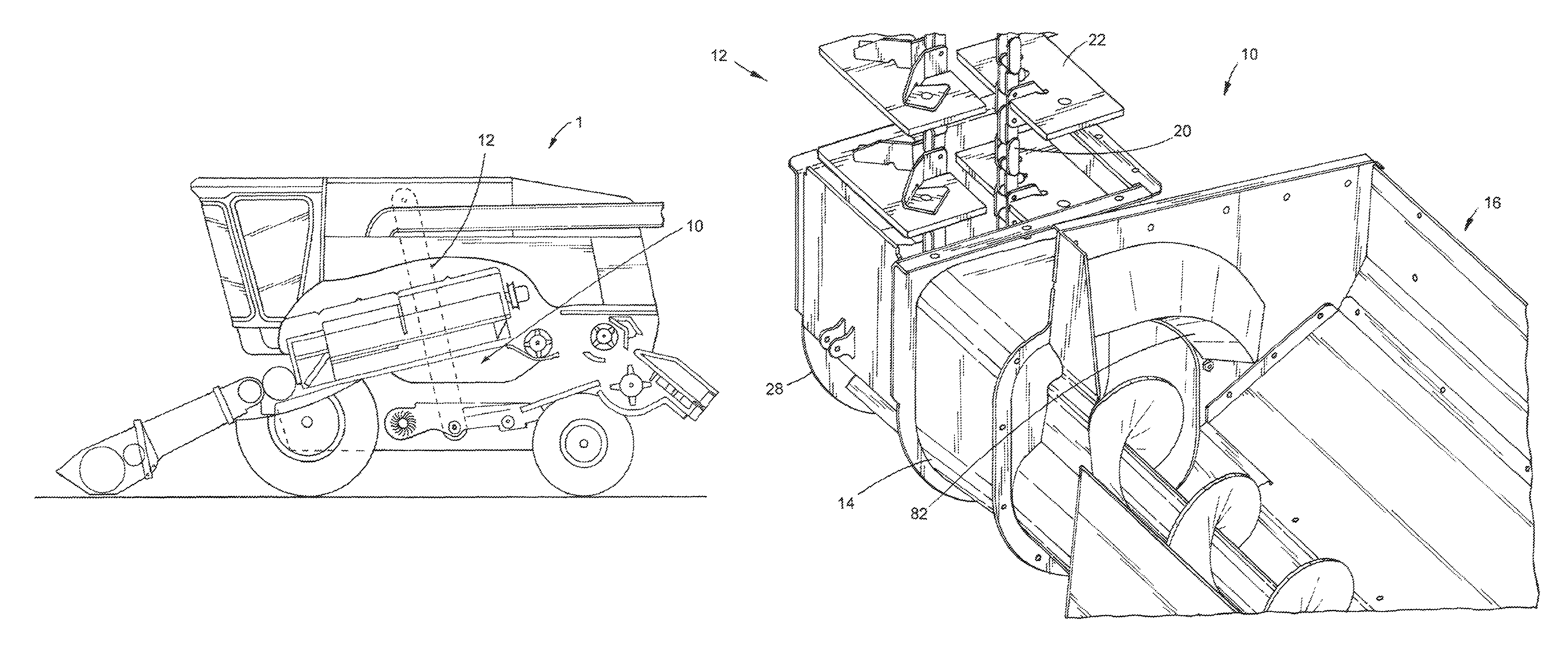
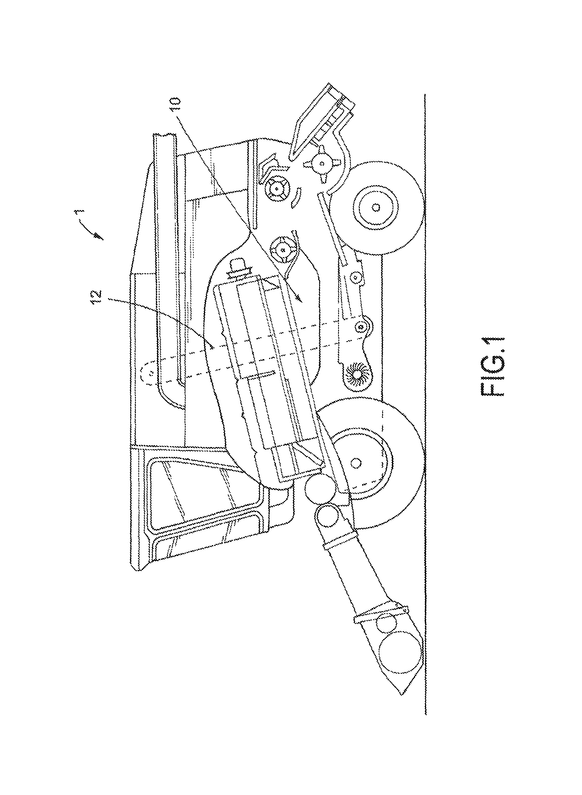
[0014]FIG. 1 is a simplified left side view of a combine harvester including a clean grain conveyor according to a preferred embodiment of the present invention;

Problems solved by technology

Such cylindrical bodies of typical transition chambers also typically have sharp edged inlet and outlet orifices which adversely affect the overall performance and efficiency of the system.
Such adverse effects include limiting the rate in which grain can be fed to the grain elevator as a result of the shape of the cylindrical transition chamber and its outlet, increased wear of grain conveying components, and damage to grain kernels.

Method used


Image

  • Grain conveyor for a combine harvester
  • Grain conveyor for a combine harvester
  • Grain conveyor for a combine harvester

Examples


Embodiment Construction

[0031]Reference will now be made in detail to a preferred embodiment of the present invention illustrated in the accompanying drawings. Wherever possible, the same or like reference numbers will be used throughout the drawings to refer to the same or like features. It should be noted that the drawings are in simplified form and are not drawn to precise scale. In reference to the disclosure herein, for purposes of convenience and clarity only, directional terms such as top, bottom, above, below, right, left, front, rear and diagonal, are used with respect to the accompanying drawings. Such directional terms used in conjunction with the following description of the drawings should not be construed to limit the scope of the invention in any manner not explicitly set forth. Additionally, the term “a,” as used in the specification, means “at least one.” The terminology includes the words above specifically mentioned, derivatives thereof, and words of similar import.

[0032]The terms “grain...


PUM


Abstract

A grain conveyor for a combine harvester capable of increasing capacity and reducing component wear is disclosed. The grain conveyor includes a grain elevator, a transition chamber and an auger assembly. The grain elevator has an inlet for receiving a flow of grain. The transition chamber includes an inlet and an outlet in fluid communication with the transition chamber inlet and the grain elevator inlet. The transition chamber outlet has an asymmetric non-circular opening larger than the non-cylindrical opening of the transition chamber inlet. The auger assembly is operatively connected to the transition chamber and includes an inlet for receiving a flow of grain and an outlet in fluid communication with the transition chamber inlet.

Description

BACKGROUND OF THE INVENTION[0001]The present invention relates generally to a grain conveyor for use with combine harvesters. In particular, the present invention relates to an improved grain conveyor having an asymmetric transition chamber between a clean grain trough and a clean grain elevator.[0002]Combines are used to harvest agricultural crops such as corn, soybeans, wheat and other grain crops. As the combine is driven through crop fields, the combine cuts the crop, separates the desired crop from the undesired waste, stores the crop, and discards the waste.[0003]In a typical combine, a header is mounted to the front of the combine to gather the crop and feed the crop into the combine for processing. As the combine is driven through the field, the crop material is collected by the header and deposited into a feeder housing. The crop material is then transported upwardly and into the combine by a feed elevator located within the feeder housing. The crop material then passes thr...

Claims


Application Information

Patent Timeline
Patent Type & Authority Patents(United States)
IPC IPC(8): A01F12/46
CPCH04L27/01A01D61/008A01F12/46A01F12/52
Inventor MCCULLY, WILLIAM MARKBANKS, JR., CLAYTON E.VEIKLE, ERIC EMERSONLINDE, KARL ROBERTCANNEGIETER, TODD ALLENHILLEN, CURTIS FREDERICKDUQUESNE, FRANK R. G.
Owner BLUE LEAF I P INC
Why Eureka
Try Eureka