Batch type microwave grain dryer and drying method

A grain dryer and grain technology, applied in non-progressive dryers, dryers, drying solid materials, etc., can solve the problems of reduced grain drying quality, reduced drying efficiency, and small drying and ventilation area, so as to reduce excessive heating The risk of drying, the effect of ensuring drying quality and shortening drying time

Pending Publication Date: 2019-08-06
ZOOMLION HEAVY MASCH CO LTD
View PDF9 Cites 4 Cited by
  • Summary
  • Abstract
  • Description
  • Claims
  • Application Information

AI Technical Summary

Problems solved by technology

The traditional microwave drying process is to pass the materials collectively through the drying chamber, and add a microwave heating device in the drying chamber for direct drying. Not only the microwave utilization rate is low, the drying efficiency is low, the structure matching is unreasonable, it is easy to cause local microwave radiation intensity, resulting in local temperature. If the drying temperature is too high, the risk of carbonization or fire will be formed. If the drying temperature is too high, the cracking rate of the grain will be increased, the drying quality of the grain will be reduced, and the nutritional content of the grain will be destroyed, which is not suitable for industrial applications.
[0003] The prior art most related to the present invention is the patent titled "A Grain Drying Device" (Patent No.: 201710035017.4). The microwave transmitting antenna is directly installed in the drying chamber. The ventilation area is small, and the grains are ventilated and dried immediately after microwave heating. The drying efficiency is low. The drying gas enters the drying room from the natural gas in the outdoor environment to ventilate and dry. The drying efficiency is greatly affected by the ambient temperature and humidity, especially in autumn and winter. Decreases sharply and does not dry properly
The above factors directly lead to low drying efficiency of grain, which is not suitable for industrial application

Method used


Image

  • Batch type microwave grain dryer and drying method
  • Batch type microwave grain dryer and drying method
  • Batch type microwave grain dryer and drying method

Examples


Embodiment 1

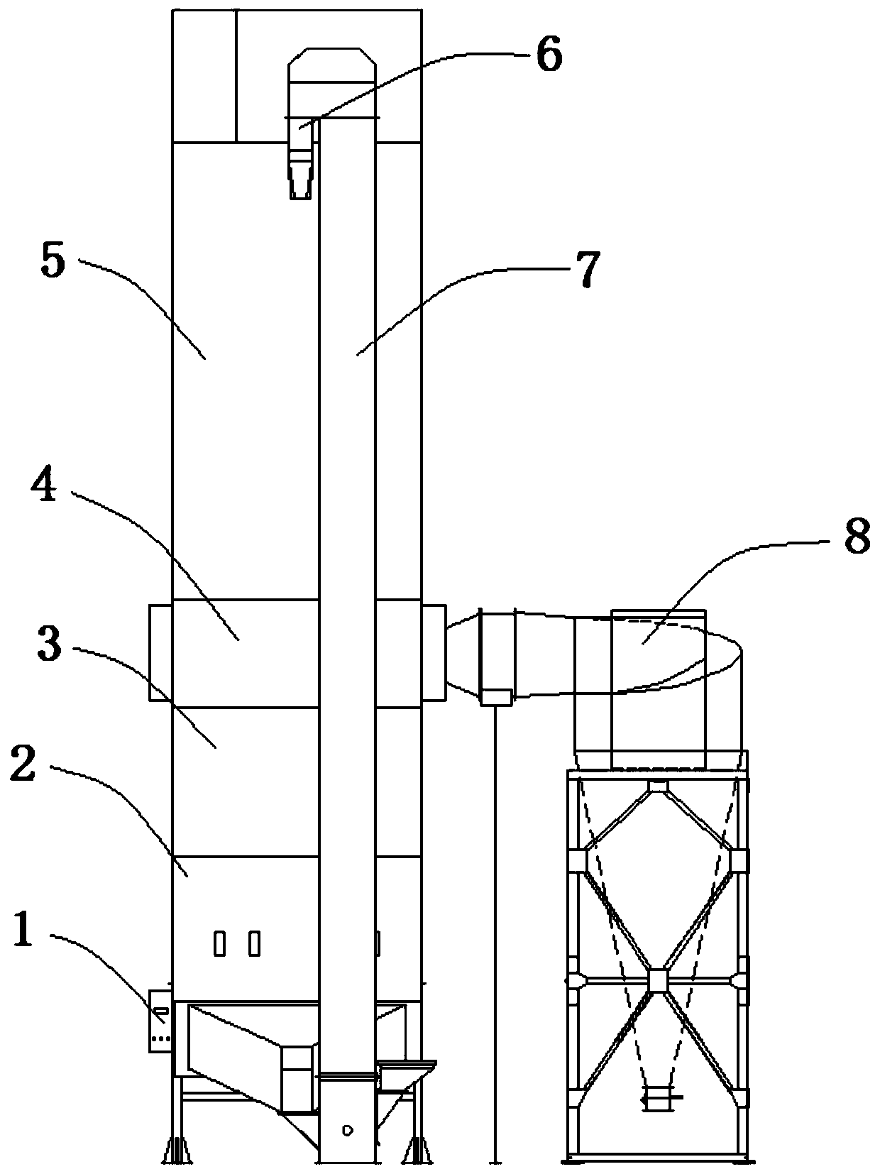
[0034] Batch Microwave Grain Dryer

[0035] Such as figure 1 , figure 2 As shown, a grain hoist 7 is provided, and from top to bottom, there are interconnected slowing warehouses 5, a drying chamber 4, a collection chamber 3, and a microwave heating device 2. The drying chamber 4 is used to dry and dehumidify the grain. The microwave heating device 2 is used for microwave heating of grain. The discharge port on the grain hoist 2 upper end is communicated with the slow Su warehouse 5. The upper and lower parts of the Susu warehouse are equipped with material level gauges and height gauges respectively, and the grain volume changes in the warehouse are monitored during the drying process. During implementation, the discharge port at the upper end of the grain hoist is provided with an upper auger 6, and the upper auger 6 is provided with a screw auger, an even distributor and an electric grain discharge device. The discharge port of the microwave heating device 2 is communi...

Embodiment 2

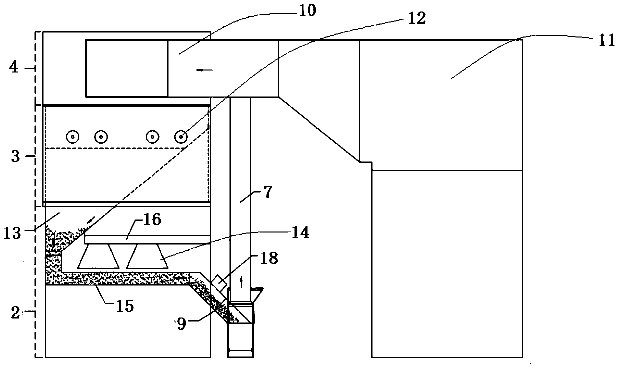
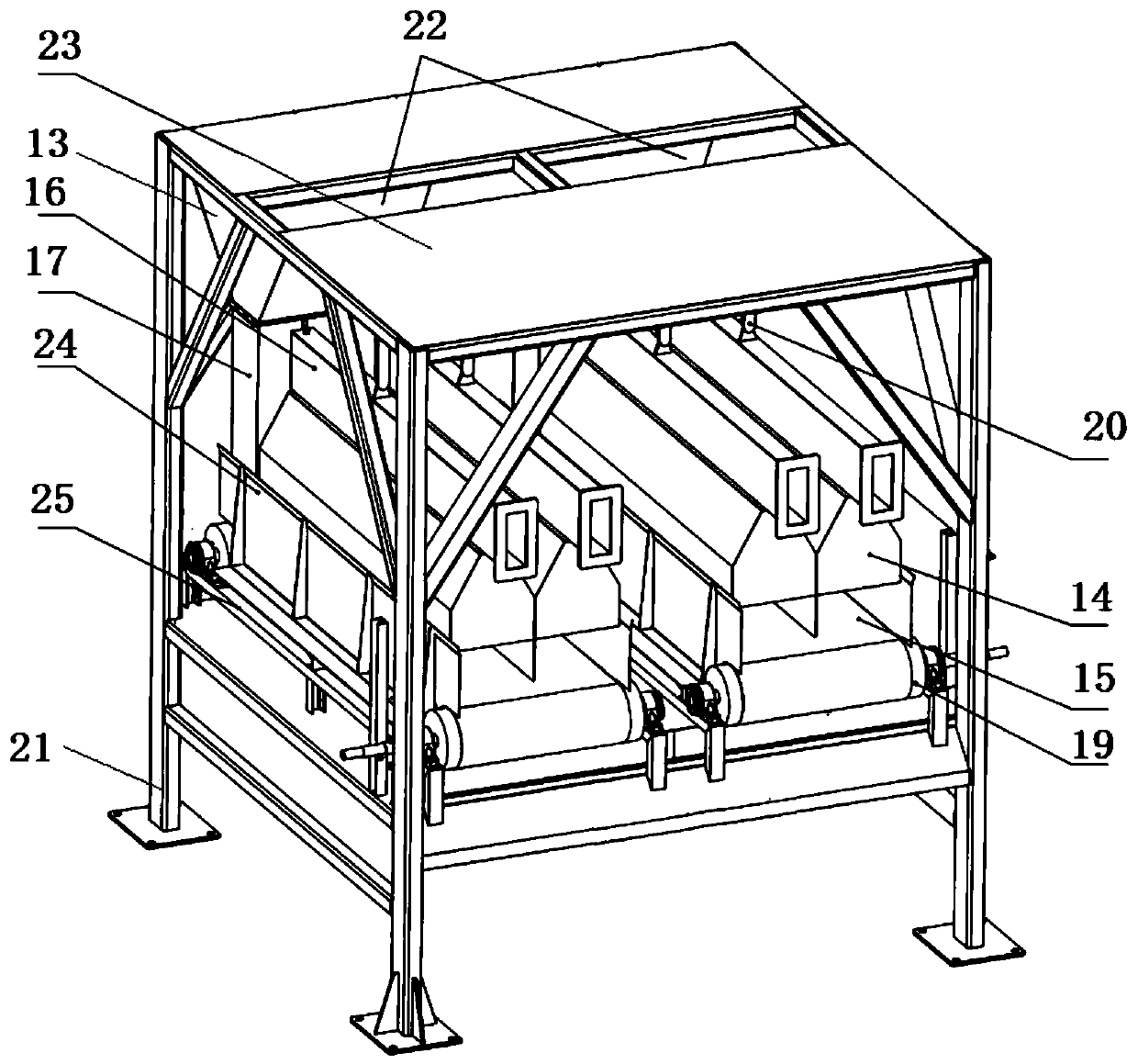
[0038] Batch Microwave Grain Dryer

[0039] The difference between the second embodiment and the first embodiment lies in the structure of the microwave heating device. Such as figure 2 , image 3 As shown, the microwave heating device comprises a collection hopper 13, a microwave heater 14 and a horizontally arranged grain conveyor belt 15, the microwave heater 14 is positioned above the grain conveyor belt 15, and the feed inlet at the top of the collection hopper 13 and the discharge at the bottom of the collection chamber 3 The mouth is connected, and the discharge port of collecting bucket 13 links to each other with the feeding end of grain conveyer belt 15, and the discharge end of grain conveyer belt 15 is connected with the feed port of grain hoist 7 lower ends through gathering box 9. The microwave heater 14 consists of a radiation box, a waveguide, and a horn-shaped transmitting antenna. The waveguide and the transmitting antenna are located in the radiation box....

Embodiment 3

[0042] Drying method based on the above-mentioned batch microwave grain dryer

[0043] The wet grain enters through the feed port of the grain hoist, and performs circulation drying. Such as Figure 5 Shown, drying method comprises the steps:

[0044] Step 1: The grain is dried and dehumidified by hot air in the drying chamber, and then enters the microwave heating device through the collection chamber through the action of the grain discharge wheel in the collection chamber;

[0045] Step 2: The grain is microwave-heated in the microwave heating device, and the inside and outside of the grain are evenly heated at the same time to accelerate the internal moisture transfer rate, and then enter the slow-sum warehouse through the grain elevator;

[0046] Step 3: The grain is tempered in the tempering warehouse, and the moisture inside the grain is fully transferred to the outside in the tempering warehouse and then enters the drying room; the tempering time is not less than 5 t...


PUM


Abstract

The invention relates to a batch type microwave grain dryer and a drying method. The batch type microwave grain dryer is provided with a grain elevator, and a tempering bin, a drying chamber, a collecting chamber and a microwave heating device which are connected with each other are sequentially arranged from top to bottom, wherein the drying chamber is used for drying and dehumidifying grains, and the microwave heating device is used for microwave heating of grains; a discharging port at the upper end of the grain elevator is connected with the tempering bin, and a discharging port of the microwave heating device is connected with a feeding port at the lower end of the grain elevator. According to the batch type microwave grain dryer, the grain discharging speed, the microwave heating radiation frequency and the temperature and humidity of the drying chamber hot air are controlled according to grain temperature and grain moisture, so that variable temperature and variable frequency drying are realized, and the drying efficiency of the grain is effectively improved.

Description

technical field [0001] The invention relates to a batch type microwave grain dryer and a drying method. Background technique [0002] Microwave is a kind of electromagnetic wave, which is an electromagnetic wave with a frequency from 300MHz to 300GHz. Its direction and size change periodically with time, and it is a penetrating electromagnetic wave. It has the characteristics of high frequency, short wavelength and high frequency. Microwave heating utilizes the principle of dielectric loss. Since water is a substance that strongly absorbs microwaves, the loss factor of water is much larger than that of dry matter. In a strong microwave field, the moisture in the material to be heated will move violently with the absorption of microwave energy, and a large amount of heat energy will be generated due to the violent movement and high-speed collision, which will provide a large amount of heat energy required for the transpiration of water, making its temperature Rising rapidl...

Claims


Application Information

Patent Timeline
Patent Type & Authority Applications(China)
IPC IPC(8): F26B11/00F26B21/10F26B21/08F26B25/22F26B3/347
CPCF26B11/00F26B21/10F26B21/08F26B25/22F26B3/347
Inventor 王辉李庆金李耿李小化孔凡飞张鹏杨刚
Owner ZOOMLION HEAVY MASCH CO LTD
Why Eureka
Try Eureka