Agricultural drying mechanism and automatic control method thereof

A drying and mechanical technology, applied in the field of agricultural drying machinery and its automatic control, agricultural machinery for grain drying and its automatic control, can solve the problems of poor drying effect, high air moisture content, increased operating cost and energy consumption, etc. Achieve the effect of improving product quality, improving air flow, and improving utilization.

Inactive Publication Date: 2017-12-08
毛强平
View PDF8 Cites 4 Cited by
  • Summary
  • Abstract
  • Description
  • Claims
  • Application Information

AI Technical Summary

Problems solved by technology

[0003] In the above process, there are several key factors: 1. The moisture content of the air generated during the drying process is relatively high. When this part of the air is directly applied to the subsequent slow recovery process, the drying effect will not be good.
2. During the drying process, due to the fast drying spe

Method used


Image

  • Agricultural drying mechanism and automatic control method thereof
  • Agricultural drying mechanism and automatic control method thereof
  • Agricultural drying mechanism and automatic control method thereof

Examples


Example Embodiment

[0055] Example 1

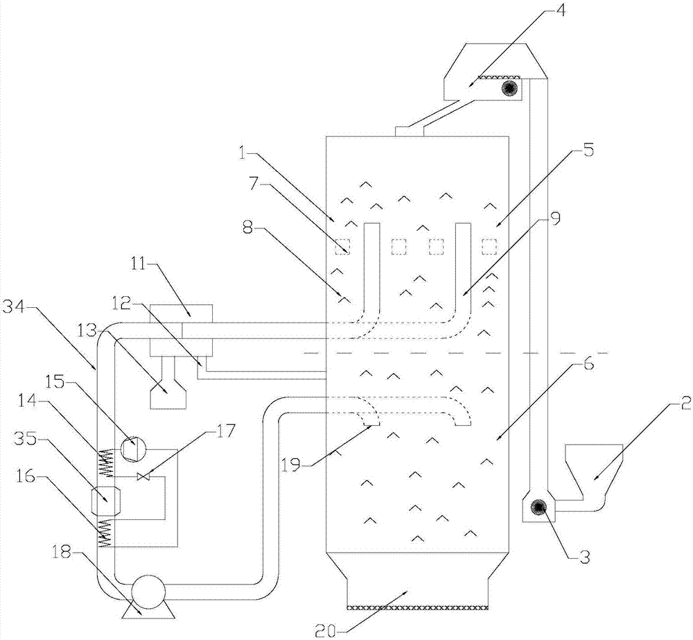
[0056] The structure of the drying machine provided by the present invention is as follows figure 1 Shown, including:

[0057] The main body 1 of the drying silo is composed of a drying silo 5 located on the upper layer and a slow silo 6 located on the lower layer, and the drying silo 5 and the slow sluice storage 6 are connected;

[0058] Feeding device 2 is used to feed grains into it, which can be a funnel and other equipment;

[0059] The lifting device 3 connects the feeding device 2 with the feeding device 4, and is used to lift the grain from the feeding device 2 to the feeding device 4 located on the upper part of the drying bin main body 1. The lifting device 3 can be a conveyor belt and other devices;

[0060] The feeding device 4 is used for feeding grains into the drying bin 5, and equipment such as a vibrating screen can be used;
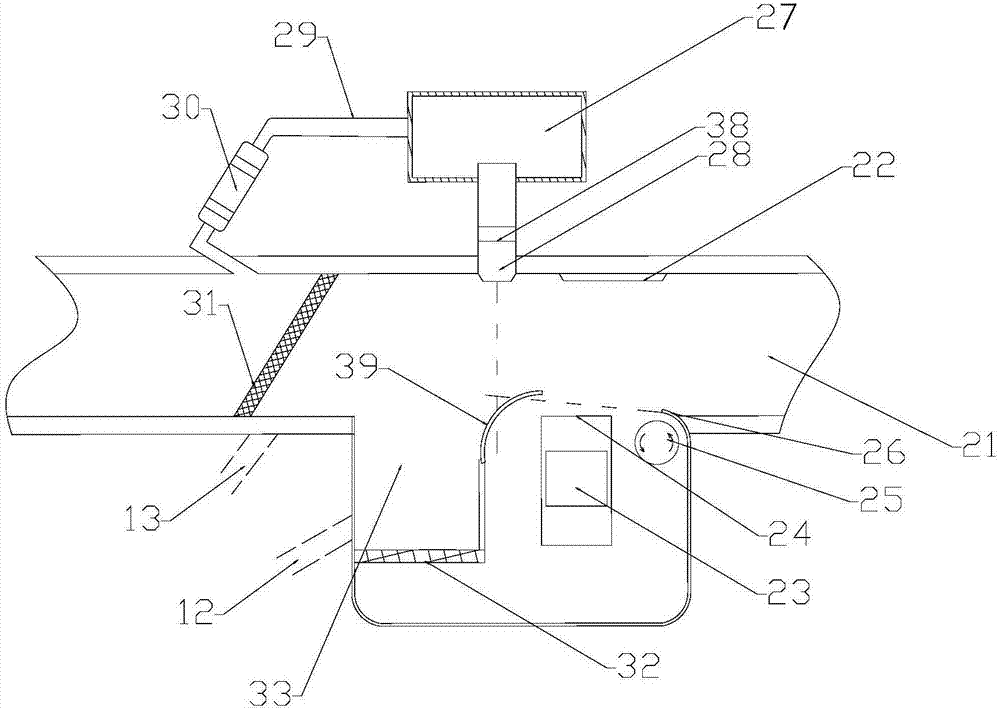
[0061] The barriers 8 are distributed in the drying silos 5 and the slow silos 6 to block the grains and prevent them from fa...

Example Embodiment

[0078] Example 2

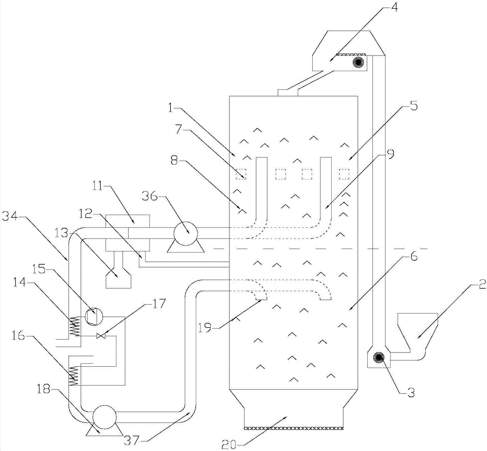
[0079] Another drying machine provided by the present invention, such as image 3 Shown, with figure 1 The main difference of the device shown is: the outlet of the powder separator 11 is provided with an exhaust pipe 34, and the exhaust pipe 34 is provided with an evaporator 14 and a suction pump 36; an air supply pipe 37 is connected to the upper part of the slow-storage warehouse 6 for supply A suction pump 18 is provided in the air pipe 37 to send outside air into the slow-storage warehouse 6; a condenser 16 is also provided in the air supply pipe 37; one end of the evaporator 14 passes through the compressor 15 and the condenser 16 in turn , The expansion valve 17 is connected back to the other end of the evaporator 14, forming a closed cycle.

[0080] In the exhaust duct 34 is the air that has passed through the grains and skin fragments. After the heat energy is used by the evaporator 14, the heat energy is directly transferred to the air directly collect...


PUM

PropertyMeasurementUnit
Diameteraaaaaaaaaa

Abstract

The invention relates to an agricultural drying mechanism and an automatic control method thereof, in particular relates to an agricultural mechanism for drying grain and an automatic control method thereof, and belongs to the technical field of agricultural mechanisms. The drying mechanism is mainly applied to the grain drying; water produced in the grain drying process is drained through the drying mechanism during the drying stage, and meanwhile, the air is returned to a tempering bin after the heat is recovered from the heat, thus the requirement on low-temperature and high-flow-rate drying air in the tempering process is met, and the grain crackle ratio is decreased; meanwhile, the grains carried out during the drying process can be separated out and returned to the tempering bin, so that the grain utilization rate is increased.

Description

technical field [0001] The invention relates to an agricultural drying machine and an automatic control method thereof, in particular to an agricultural machine used for grain drying and an automatic control method thereof, and belongs to the technical field of agricultural machinery. Background technique [0002] In the process of drying grains (rice, wheat, millet, corn, etc.), the main drying process is divided into two stages, one is the drying stage, the process of this stage is mainly the transfer and vaporization of the moisture on the surface of the grain, The moisture drying process is fast, and air with high water content will be produced; the latter section is the slow su section, which is mainly the process of transferring the moisture inside the grain to the outside. Due to the slow transfer process, if higher temperature and smaller flow rate are used When there is too much air, the volume will cause the surface of the grain to crack (burst rate). Therefore, ...

Claims


Application Information

Patent Timeline
IPC IPC(8): F26B17/16F26B21/00F26B21/08F26B23/00F26B25/00A23B9/08
CPCA23B9/08F26B17/12F26B17/16F26B21/001F26B21/003F26B21/004F26B21/086F26B23/004F26B25/002F26B25/007F26B2200/06Y02A40/90Y02P70/10
Inventor 不公告发明人
Owner 毛强平
Why Eureka
Try Eureka