
System and method for return electrode monitoring

a technology of return electrode and monitoring system, which is applied in the field of system and method for monitoring return electrode, can solve the problems of increasing the current density of the adhered portion, increasing the probability of tissue damage, and reducing the contact area of the electrode with the patien

Active Publication Date: 2014-08-12
TYCO HEALTHCARE GRP LP
View PDF293 Cites 179 Cited by
  • Summary
  • Abstract
  • Description
  • Claims
  • Application Information

AI Technical Summary

Benefits of technology

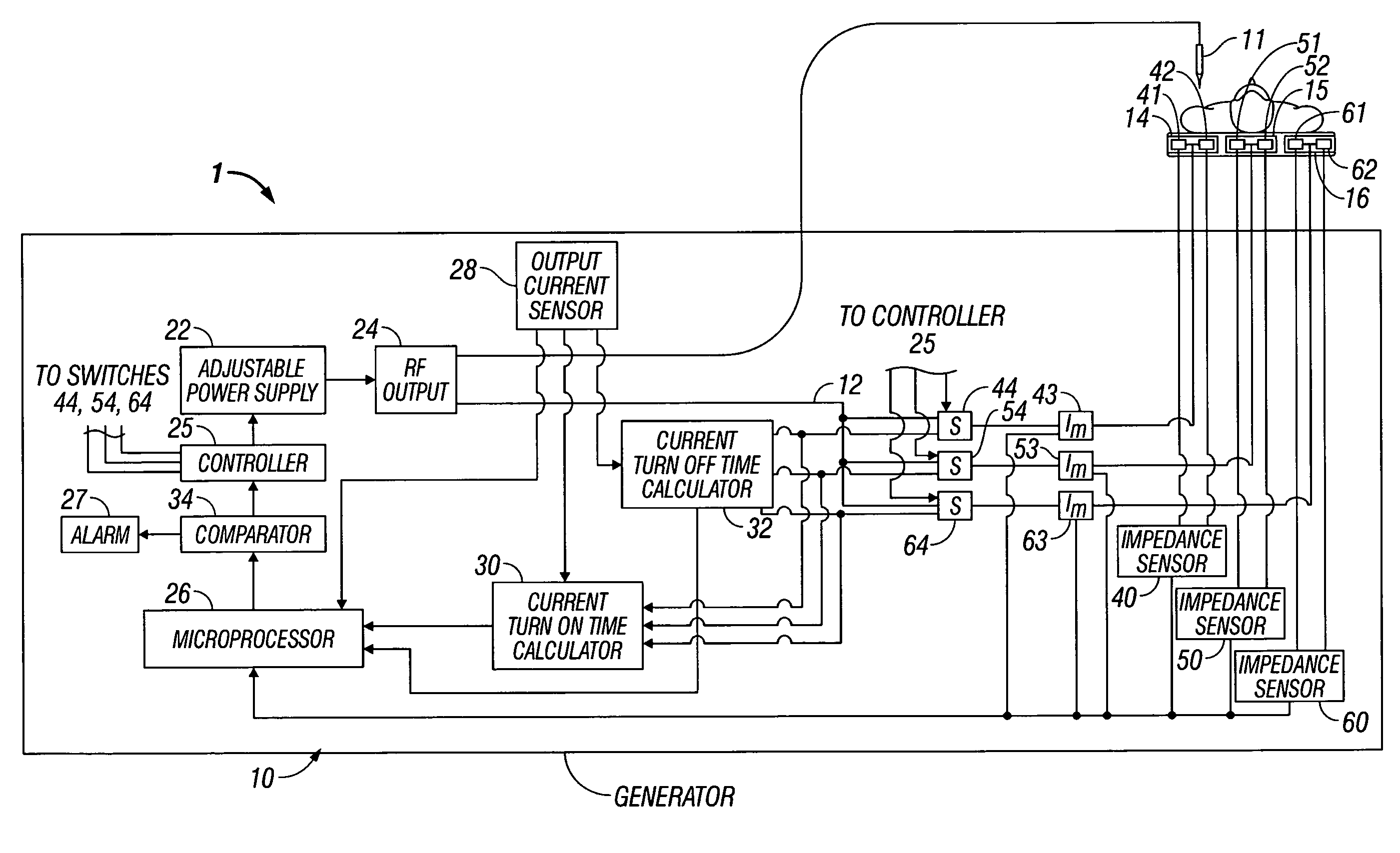
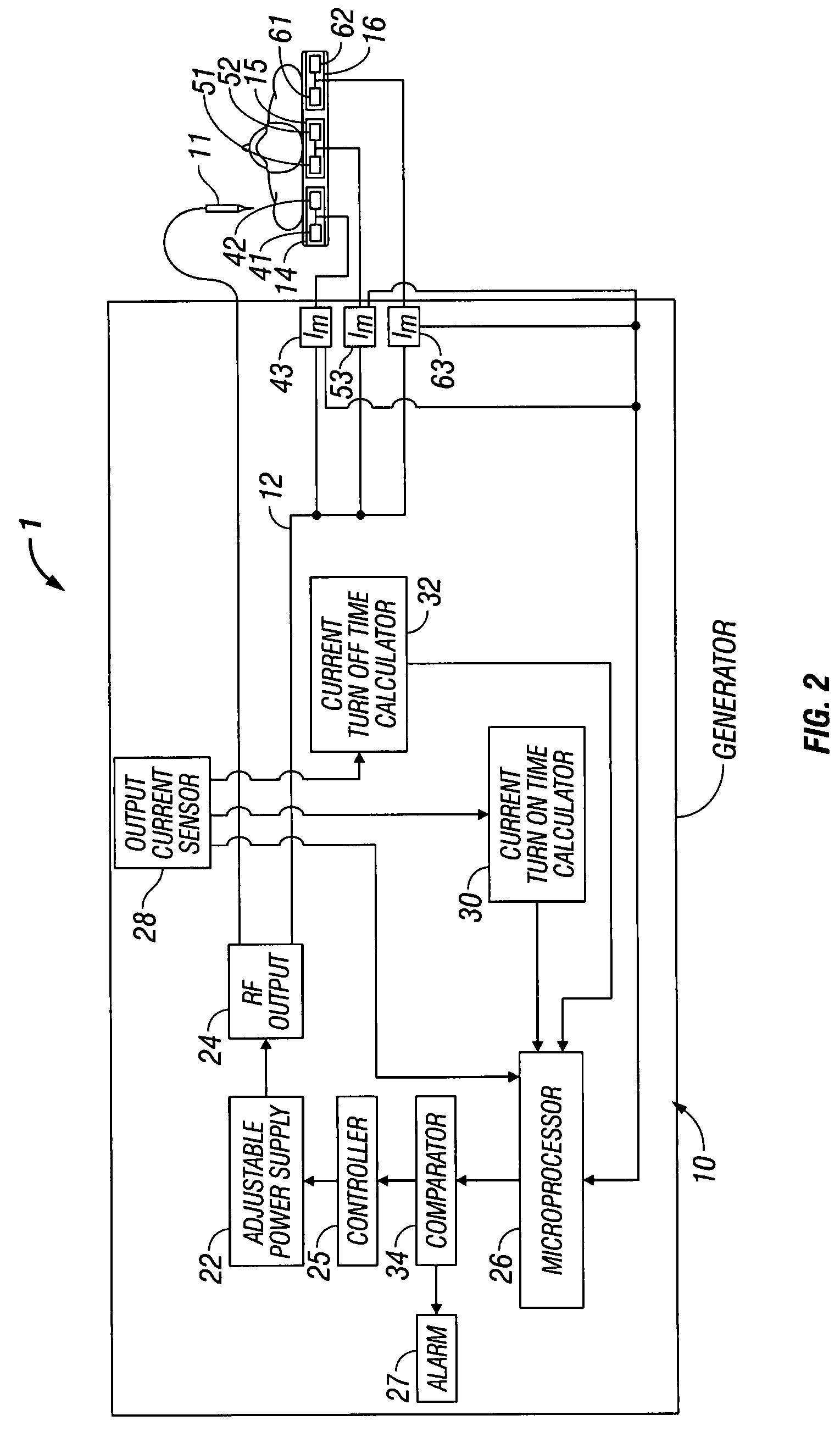
This patent describes a system that ensures that multiple return electrodes are properly attached to a patient and balances heat effects during electrosurgical procedures involving a big number of return electrodes. The system includes an electrosurgical generator, multiple return electrodes, a current monitor, a switch, and an impedance sensor. The generator monitors the current passing through each return electrode and checks if the current load exceeds a certain threshold, at which point the return electrode is removed from the circuit. This helps to avoid any harmful effects on the patient tissue during the procedure.

Problems solved by technology

However, one problem with these adhesive electrodes was that if a portion peeled from the patient, the contact area of the electrode with the patient decreased, thereby increasing the current density at the adhered portion and, in turn, increasing the heat applied to the tissue.
This risked burning the patient in the area under the adhered portion of the return electrode if the tissue was heated beyond the point where circulation of blood could cool the skin.
This extended duration for a high total current value may create a potential for alternate site burns due to return electrode pad heating.
Further, the use of multiple return electrodes may also pose an additional potential problem—the increase in temperature under each of the return electrodes is not uniform, e.g., there is a thermal imbalance among the multiple return electrodes.
This condition may generate an imbalance of current among each of the return electrodes resulting in an imbalance of thermal rise on the return electrodes.

Method used


Image

  • System and method for return electrode monitoring
  • System and method for return electrode monitoring
  • System and method for return electrode monitoring

Examples


Embodiment Construction

[0020]Embodiments of the present disclosure are described hereinbelow with reference to the accompanying drawings. In the following description, well-known functions or constructions are not described in detail to avoid obscuring the present disclosure in unnecessary detail.

[0021]Systems and methods for determining whether return electrodes are properly attached to a patient, for balancing thermal effects of multiple return electrodes, and for preventing tissue damage when using multiple return electrodes are disclosed.

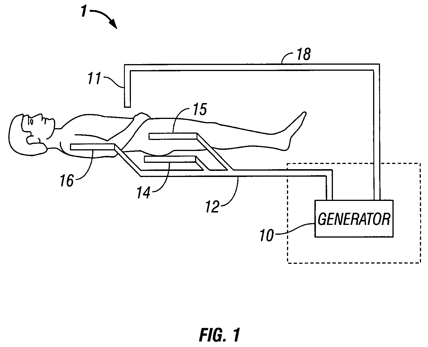
[0022]FIG. 1 is a schematic illustration of a monopolar electrosurgical system 1. The system 1 includes a surgical instrument 11, e.g., an active electrode, for treating tissue at a surgical site. Electrosurgical energy is supplied to the instrument 11 by a generator 10 via a cable 18 allowing the instrument 11 to ablate, cut or coagulate the tissue. The electrosurgical system also includes a plurality of return electrodes 14, 15 and 16 placed under the patient's back...


PUM


Abstract

A system for determining probability of tissue damage is disclosed. The system includes a plurality of return electrodes adhered to a patient and adapted to couple to an electrosurgical generator configured to generate an electrosurgical current. The system also includes a current monitor and a switching component connected in series with each of the plurality of the return electrodes. The current monitor being configured to measure the electrosurgical current passing therethrough. The system further includes a processor coupled to each of the current monitors and the switching components. The processor is configured to determine the balance of a current load among the plurality of the return electrodes and configured to control each of the switching components to adjust the current passing through each of the return electrodes to balance the current load.

Description

BACKGROUND[0001]1. Technical Field[0002]The present disclosure relates generally to a system and method for using a plurality of return electrodes during electrosurgery and, more particularly, to a system and method for balancing the various thermal effects of the plurality of return electrodes by minimizing the probability and ensuring the plurality of return electrodes are properly attached to a patient.[0003]2. Background of Related Art[0004]During electrosurgery, a source or active electrode delivers energy, such as radio frequency (RF) energy, from an electrosurgical generator to a patient and a return electrode or a plurality thereof carry current back to the electrosurgical generator. In monopolar electrosurgery, the source electrode is typically a hand-held instrument placed by the user at the surgical site and the high current density flow at this electrode creates the desired surgical effect of ablating, cutting or coagulating tissue. The patient return electrodes are plac...

Claims


Application Information

Patent Timeline
Patent Type & Authority Patents(United States)
IPC IPC(8): A61B18/12
CPCA61B2017/00119A61B2018/00875A61B2018/00755A61B18/16A61B18/1233A61B2018/1467A61B2018/162A61B2017/00026A61B2018/0072A61B2018/165A61B2018/00827A61B2018/00666
Inventor GREGG, WILLIAM N.RICK, KYLE R.
Owner TYCO HEALTHCARE GRP LP
Learn More