Fuel saving inert gas generation system

a fuel-saving, inert gas technology, applied in the field of aircraft, can solve the problems of increasing the maintenance needed for the inert gas generation system, increasing the fuel cost of the aircraft more than desired, and unlikely combustion of fuel vapors in these locations

Active Publication Date: 2014-08-12
THE BOEING CO
View PDF12 Cites 43 Cited by
  • Summary
  • Abstract
  • Description
  • Claims
  • Application Information

AI Technical Summary

Benefits of technology

[0011]In one illustrative embodiment, an apparatus comprises an air separation module and an air flow control system. The air separation module is configured to separate an inert gas from air input into the air separation module. The air flow control system is configured to control a flow of the air into the air separation module.

Problems solved by technology

Without sufficient oxygen, combustibility of fuel vapors in these locations is unlikely.
The operation of the inert gas generation system may increase fuel costs more than desired to operate the aircraft.
Further, continual use of the inert gas generation system during operation of the aircraft may increase maintenance needed for the inert gas generation system.

Method used


Image

  • Fuel saving inert gas generation system
  • Fuel saving inert gas generation system
  • Fuel saving inert gas generation system

Examples


Embodiment Construction

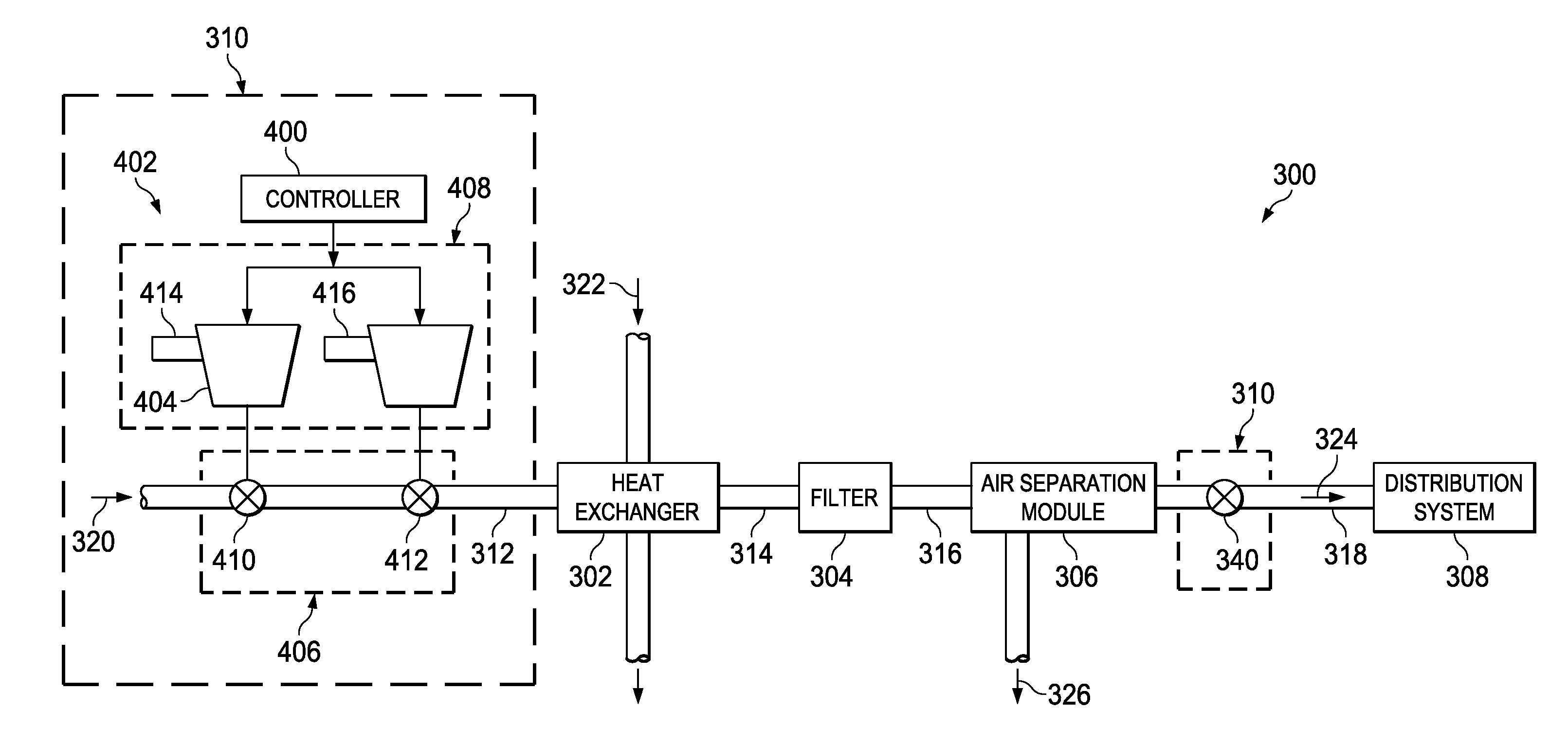
[0024]The different illustrative embodiments recognize and take into account a number of different considerations. For example, the different illustrative embodiments recognize and take into account that the amount of inert gas needed to maintain a desired level of inert gas in the fuel tanks during flight of an aircraft may change during the different phases of flight. As a result, the different illustrative embodiments recognize and take into account that it may be desirable to change the amount of inert gas generation during different phases of flight to provide the desired level of inert gas in the fuel tanks. During some phases of flight, the amount of inert gas generation needed to provide a desired level of inertness within a gas tank may be lower during other phases of flight.

[0025]For example, the different illustrative embodiments recognize and take into account that most air separation modules used in inert gas generation systems are sized for generating inert gas to high...


PUM

PropertyMeasurementUnit
operating temperatureaaaaaaaaaa
pressureaaaaaaaaaa
temperatureaaaaaaaaaa

Abstract

A method and apparatus for controlling inert gas generation. An apparatus comprises an air separation module and an air flow control system. The air separation module is configured to separate an inert gas from air input into the air separation module. The air flow control system is configured to control the flow of the air into the air separation module.

Description

GOVERNMENT LICENSE RIGHTS[0001]This application was made with United States Government support under contract number FA8615-08-3-2080 awarded by the United States Air Force. The United States Government has certain rights in this application.BACKGROUND INFORMATION[0002]1. Field[0003]The present disclosure relates generally to aircraft and, in particular, to inert gas generation systems for aircraft. Still more particularly, the present disclosure relates to a method and apparatus for controlling operation in an inert gas generation system for aircraft.[0004]2. Background[0005]Many aircraft have inert gas generation systems. An inert gas generation system may be used to render a fuel tank in an aircraft substantially inert. Fuel tanks in an aircraft may have a space above the fuel in which fuel vapors may be present. This space in the fuel tank is referred to as an ullage.[0006]The inert gas generation system is employed to reduce a possibility of combustion within this space in a fu...

Claims


Application Information

Patent Timeline
Patent Type & Authority Patents(United States)
IPC IPC(8): A62C3/08B64D37/32A62C3/06
CPCA62C3/08B01D2257/104B64D2013/0651B64D45/00B64D37/32B01D2256/10B01D2259/40003B01D2259/4575B64D2013/0681A62C3/06A62C99/0018
Inventor SNOW, JR., DONALD RAYSMITH, DAVID MICHAEL
Owner THE BOEING CO
Why Eureka
Try Eureka