Wireless power transmission/reception apparatus and method

a power transmission and reception technology, applied in the direction of exchanging data chargers, inductances, read/write/interrogation/identification systems, etc., can solve the problems of high radiation loss of radio reception technology, limited use of communication information devices, and inability to free the environment of a wireless information network from this limitation. , to achieve the effect of minimizing the unnecessary consumption of power

Active Publication Date: 2014-08-12
WITS CO LTD
View PDF26 Cites 14 Cited by
  • Summary
  • Abstract
  • Description
  • Claims
  • Application Information

AI Technical Summary

Benefits of technology

[0019]Furthermore, the present invention is intended to provide a wireless power transmission / reception apparatus and method, which employ a power amplifier enabling ON / OFF control, thus minimizing the unnecessary consumption of power.

Problems solved by technology

However, most communication information devices still depend on batteries and are supplied with power by a wired power cord, and thus the use of communication information devices is limited.
Therefore, the environment of a wireless information network cannot be actually freed from this limitation until the problem of terminal power is solved.
However, radio reception technology has high radiation loss due to the consumption of power by the air, and thus the efficiency of power transmission is limited.
However, magnetic induction technology is disadvantageous in that the primary coil of the transmitting end and the secondary coil of the receiving end must be located adjacent to each other within a short distance of about several mm so as to transmit power.
Furthermore, magnetic induction technology is disadvantageous in that the efficiency of power transmission rapidly changes according to the alignment of the primary coil of the transmitting end and the secondary coil of the receiving end, and in that the amount of heat generated is large.
In other words, magnetic resonance technology is disadvantageous because the efficiency of power transmission rapidly changes depending on whether impedance matching has been realized or whether the resonant frequencies of the LC circuit of the transmitting end and the LC circuit of the receiving end are identical to each other.
In particular, impedance mismatching and transmission efficiency at low output power, which are caused by variations in the distance between the transmitting end and the receiving end, become principal factors which interfere with optimal wireless power transmission in wireless power transmission.
However, when the communication devices (for example, transceivers) are separately mounted, problems arise in that costs required for a wireless power transmission apparatus increase, and the construction of the apparatus becomes complicated.
Further, a power amplifier for amplifying the output power to improve transmission efficiency at low output power must always be kept turned on even when power amplification is not required, and thus this driving of the power amplifier wastes power unnecessarily.

Method used


Image

  • Wireless power transmission/reception apparatus and method
  • Wireless power transmission/reception apparatus and method
  • Wireless power transmission/reception apparatus and method

Examples


Embodiment Construction

[0042]The above and other objects, features and advantages of the present invention will be more clearly understood from the following detailed description taken in conjunction with the accompanying drawings.

[0043]Prior to giving the description, the terms and words used in the present specification and claims should not be interpreted as being limited to their typical meaning based on the dictionary definitions thereof, but should be interpreted to have the meaning and concept relevant to the technical spirit of the present invention on the basis of the principle by which the inventor can suitably define the implications of terms in the way which best describes the invention.

[0044]Hereinafter, embodiments of the present invention will be described in detail with reference to the attached drawings.

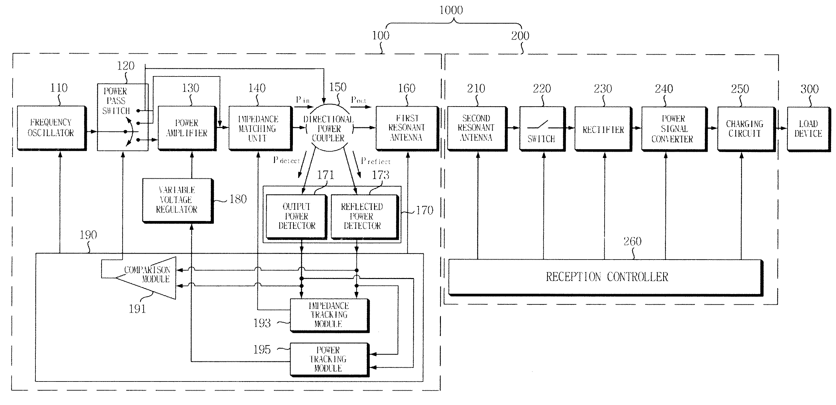
[0045]FIG. 1 is a block diagram schematically showing the construction of a wireless power transmission / reception apparatus according to an embodiment of the present invention.

[0046]Referr...


PUM


Abstract

A wireless power transmission / reception apparatus includes a wireless power transmission unit. The transmission unit is configured to generate a wireless power signal to be transmitted, transmit the wireless power signal using magnetic resonance, receive a reflected wireless power signal from a wireless power reception unit, determine whether a load device is present, and transmit a further wireless power signal when it is determined that the load device is present in such a way that impedance and output power depending on variation in a distance to the load device are tracked, and wireless power is supplied to the load device in an optimized state. Accordingly, a separate transceiver module is not provided for the purpose of performing communication between a transmitting end and a receiving end, and a reception environment is automatically detected, thus enabling wireless power to be transmitted in an optimal wireless power transmission state.

Description

CROSS REFERENCE TO RELATED APPLICATION[0001]This application claims the benefit of Korean Patent Application No. 10-2010-0127537, filed on Dec. 14, 2010, entitled “Wireless power transmission apparatus and transmission method thereof”, which is hereby incorporated by reference in its entirety into this application.BACKGROUND OF THE INVENTION[0002]1. Technical Field[0003]The present invention relates to a wireless power transmission apparatus and method.[0004]2. Description of the Related Art[0005]With the development of wireless communication technology, ubiquitous information environments enabling anyone to exchange desired information anytime and anywhere have been implemented. However, most communication information devices still depend on batteries and are supplied with power by a wired power cord, and thus the use of communication information devices is limited. Therefore, the environment of a wireless information network cannot be actually freed from this limitation until the ...

Claims


Application Information

Patent Timeline
Patent Type & Authority Patents(United States)
IPC IPC(8): H04B5/00
CPCH04B5/0037H04B5/0025H04B5/0093H04B5/0075H04B5/0056H02J5/005H02J50/12H02J7/00034H02J50/20H02J50/90H02J7/00
Inventor LEE, KWANG DUKIM, JEONG HOONPARK, JOUN SUPKIM, EUNG JUHWANG, SANG HOONYOON, YOUNG SEOKPARK, CHUL GYUNYOON, JUNG HO
Owner WITS CO LTD
Why Eureka
Try Eureka