Automatic teller machine

a technology teller machine, which is applied in the direction of automatic teller machine, transportation and packaging, instruments, etc., can solve the problems of large size limited increase in the transfer path of paper medium, and complex structure of medium transfer path, so as to prevent the reduction of atm efficiency and simplify the structure of transferring paper medium

Active Publication Date: 2014-08-19
HYOSUNG TNS INC
View PDF13 Cites 2 Cited by
  • Summary
  • Abstract
  • Description
  • Claims
  • Application Information

AI Technical Summary

Benefits of technology

[0038]In an automatic teller machine (ATM) according to an embodiment of the present invention, a structure for transferring paper mediums may be simplified since the paper mediums are transferred in a bundle directly by a carriage to a dispenser portion. In addition, a jam of paper mediums generated during transfer of the paper mediums may be reduced, thereby preventing reduction in efficiency of the ATM.
[0039]According to an embodiment of the present invention, the ATM is structured in such a manner that a carriage in which paper mediums are stacked is directly transferred to a plurality of dispenser portions along movement paths of a case. Therefore, control of a dispensing operation of the ATM may be simplified, and a dispensing time for the paper mediums may be reduced. That is, the dispensing operation for the paper mediums may be quickly performed.
[0040]In the ATM according to an embodiment of the present invention, since the carriage is transferred to a plurality of dispenser portions along the movement paths, the paper mediums may be dispensed to several positions of the ATM. Also, the ATM may be applied in various environments.
[0041]In the ATM according to an embodiment of the present invention, an advancing direction of a carriage is conveniently adjusted by a rotor. Therefore, the carriage may be conveniently disposed at any one of a medium transfer unit, dispenser portions, and a retract box. Thus, since the movement paths of the carriage are conveniently selected and converted by rotation of the rotor, operation of the ATM may be simplified, consequently facilitating control of the ATM.
[0042]In the ATM according to an embodiment of the present invention, paper mediums are transferred to the carriage or a medium collection unit according to a detection value of a medium inspection unit. That is, normal paper mediums may be transferred to the carriage while abnormal paper mediums are transferred to the medium collection unit.
[0043]Therefore, while the paper mediums are being normally stacked in the carriage by the medium transfer unit, paper mediums determined to be abnormal by the medium inspection unit may be collected to the medium collection unit before being stacked in the carriage. Thus, a dedicated operation mode for collecting abnormal paper mediums is unnecessary. As a result, the operational efficiency of the ATM may be maximized.
[0038]In an automatic teller machine (ATM) according to an embodiment of the present invention, a structure for transferring paper mediums may be simplified since the paper mediums are transferred in a bundle directly by a carriage to a dispenser portion. In addition, a jam of paper mediums generated during transfer of the paper mediums may be reduced, thereby preventing reduction in efficiency of the ATM.
[0038]In an automatic teller machine (ATM) according to an embodiment of the present invention, a structure for transferring paper mediums may be simplified since the paper mediums are transferred in a bundle directly by a carriage to a dispenser portion. In addition, a jam of paper mediums generated during transfer of the paper mediums may be reduced, thereby preventing reduction in efficiency of the ATM.

Problems solved by technology

The medium transfer path is very complicated in structure and control.
Also, the entire size of the medium transfer path is large.
Therefore, increase in the transfer path for the paper mediums is limited.
In addition, a paper jam frequently occurs in a transfer unit.
However, when the rejected medium storage unit and the retracted medium storage unit are separated, the overall structure of the ATM becomes complicated and the entire size is increased, accordingly requiring a larger installation space.
Moreover, cost is increased.

Method used


Image

  • Automatic teller machine
  • Automatic teller machine
  • Automatic teller machine

Examples


Embodiment Construction

[0054]Reference will now be made in detail to embodiments of the present invention, examples of which are illustrated in the accompanying drawings, wherein like reference numerals refer to the like elements throughout. However, the scope of the present invention is not limited to the embodiments.

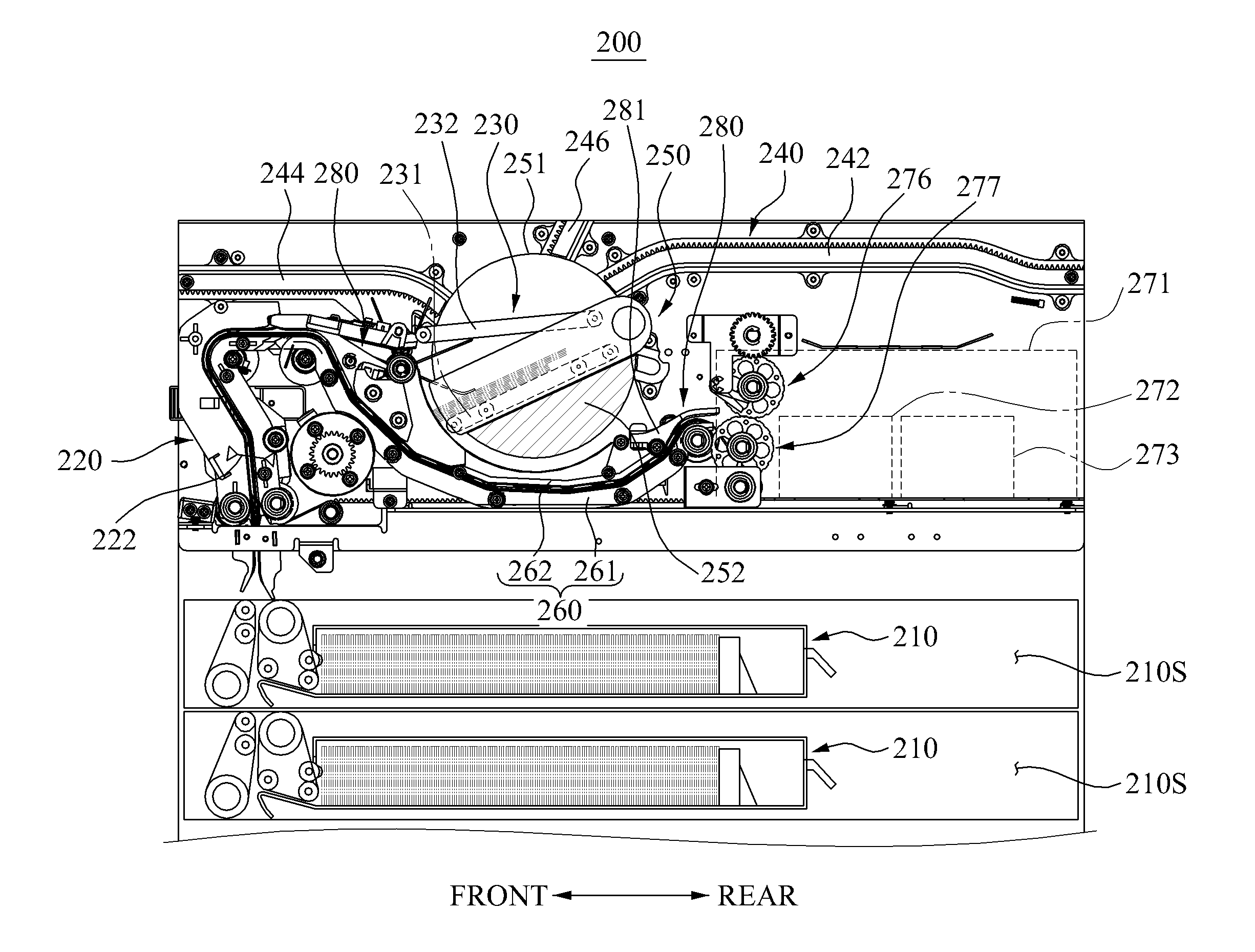
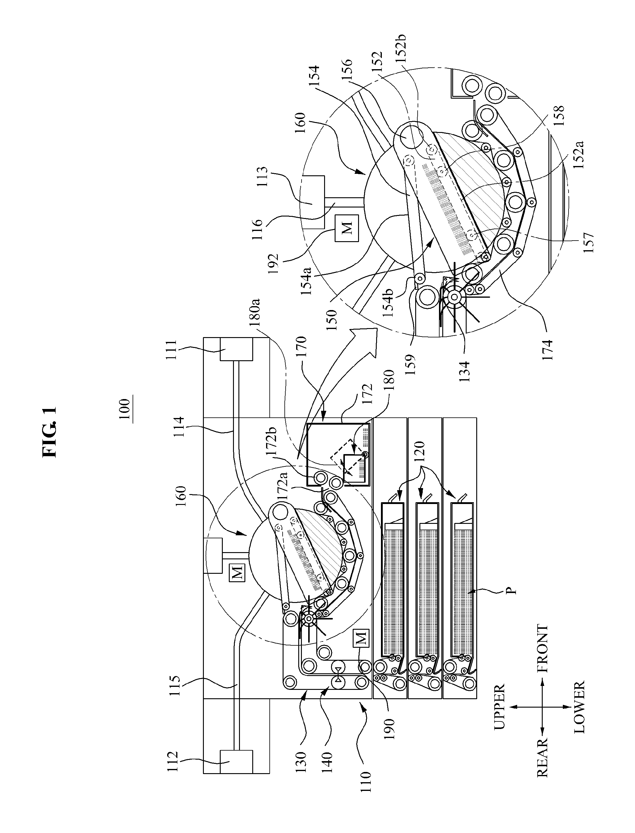
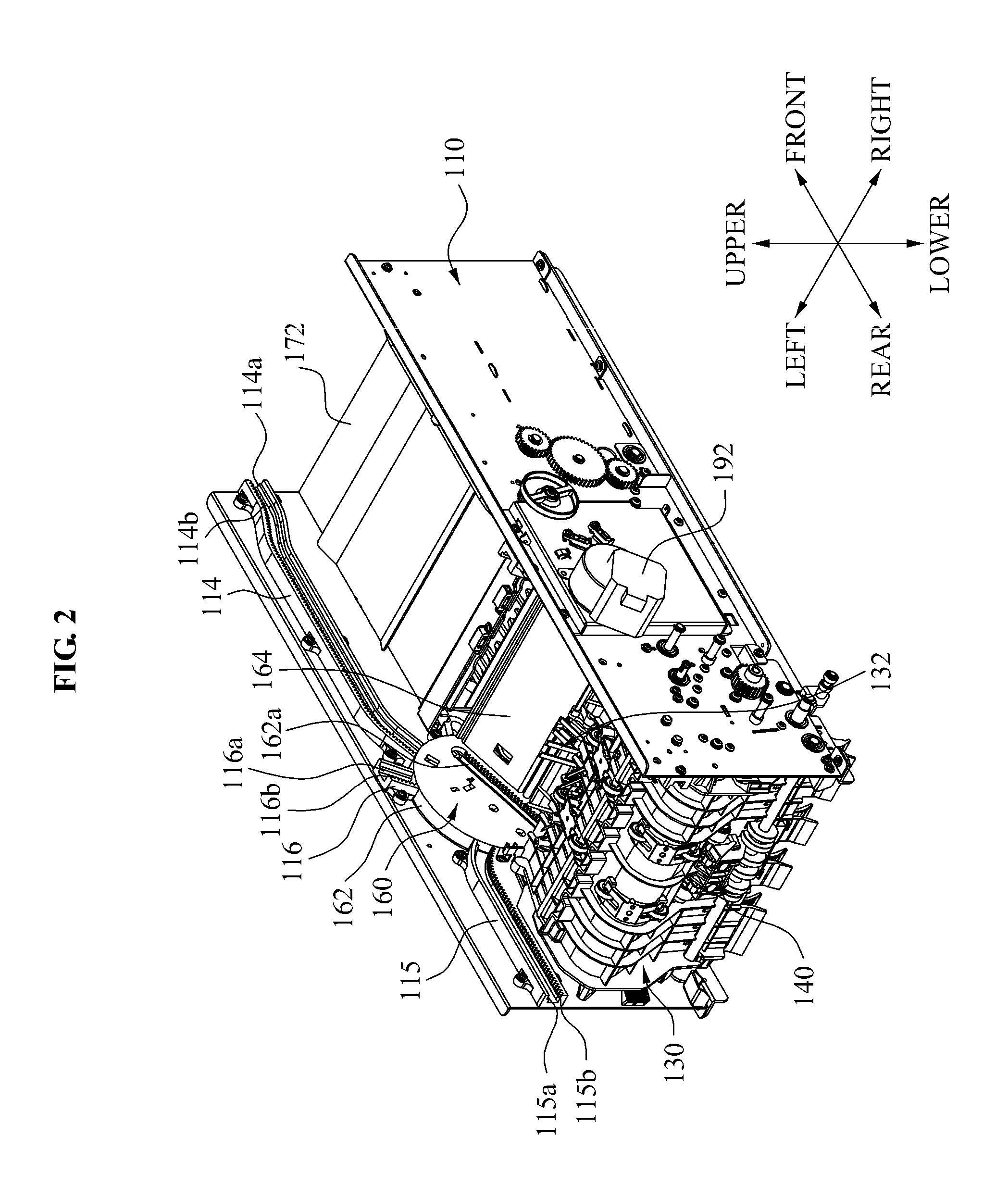
[0055]FIG. 1 is a structure view schematically illustrating an automatic teller machine (ATM) 100 according to an embodiment of the present invention. FIG. 2 is a perspective view illustrating main parts of the ATM 100 of FIG. 1. FIG. 3 is a plan view illustrating main parts of the ATM 100 of FIG. 2. FIGS. 4 to 8 are views illustrating operational states of main parts of the ATM 100 shown in FIG. 2.

[0056]Referring to FIG. 1, the ATM 100 includes a case 110, a medium storage unit 120, a medium transfer unit 130, a medium inspection unit 140, a carriage 150, a rotor 160, and a medium collection unit 170. In the following description, the ATM 100 will be limitedly described as a cash dispenser....


PUM

PropertyMeasurementUnit
lengthaaaaaaaaaa
pressing forceaaaaaaaaaa
areaaaaaaaaaaa

Abstract

An automatic teller machine (ATM) may temporarily stack paper mediums in a carriage, adjust an advancing direction of the carriage by rotating the carriage by a rotor, and dispense the paper mediums to one of a plurality of dispenser portions by the carriage moving along movement paths. In addition, since a discharge path for paper medium being discharged from a rejected medium transfer portion to a collected medium storage portion and a discharge path for paper medium being discharged from the carriage to the collected medium storage portion are formed in a common discharge space, paper mediums detected to be abnormal and rejected and paper mediums not received by the dispenser portions but retracted may be stored in one place. Consequently, the structure may be simplified.

Description

TECHNICAL FIELD[0001]The present invention relates to an automatic teller machine (ATM), and more particularly, to an ATM capable of reducing a jam of paper mediums, simplifying an inner structure and a money withdrawal operation, and collecting a rejected paper medium and a retracted paper medium during transfer along a medium transfer unit in one space.BACKGROUND ART[0002]Generally, an automatic teller machine (ATM) refers to an automated apparatus providing fundamental monetary services, such as payment and withdrawal of cash and check, using a card or a bankbook regardless of time and places without a bank teller. Recently, use of the ATM is not limited to banking facilities such as banks but expanded to convenience stores, department stores, and other public places.[0003]The ATM may be classified into a cash dispenser, a cash receiver, and a cash dispenser and receiver. In these days, the ATM is used for not only payment and withdrawal of cash but also payment and withdrawal of...

Claims


Application Information

Patent Timeline
Patent Type & Authority Patents(United States)
IPC IPC(8): G07F19/00
CPCG07D11/0003B65H29/58B65H31/3027B65H2405/35B65H2701/1912G07F19/20B65H31/24B65H31/3063B65H2301/4213B65H2301/4474B65H2402/31B65H2404/2693B65H2404/693B65H31/3045G07D11/10B65H2220/01B65H2220/02
Inventor CHA, JIN HWANLEE, WON JOONLEE, DONG SIK
Owner HYOSUNG TNS INC
Why Eureka
Try Eureka