Automotive vehicle transmission systems

a transmission system and vehicle technology, applied in the direction of engine-driven generator propulsion, process and machine control, electric devices, etc., can solve the problems of increasing the number of components and overall complexity, increasing mechanical complexity, and having to change transmission oil relatively frequently, so as to avoid inefficiency

Inactive Publication Date: 2007-02-06
DRIVETEC (UK) LTD
View PDF23 Cites 37 Cited by
  • Summary
  • Abstract
  • Description
  • Claims
  • Application Information

AI Technical Summary

Benefits of technology

[0023]As the output speed of the transmission system in accordance with the invention increases under the application of full rated power, the electrical power transmitted between the two motor / generators passes sequentially through zero twice and three maxima. The motor / generators must of course be sized and rated to cope with the maximum possible current loads and if, for instance, one of the maxima were at a significantly higher numerical value than the other two, this would result in the motor / generators being rated at a higher value than is consistent with the two other maxima and thus in their being larger, heavier and thus more expensive than is strictly necessary. There is a tendency for the electrical power transferred between the motor / generators at the first and fifth speeds to be greater than at the third speed and in order to avoid the inefficiency that this would entail it is preferred that the transmission system is so arranged that the power transferred between the motor / generators at the first and fifth speeds is no greater than at the third speed.

Problems solved by technology

Thus the number of components and overall complexity is considerably increased by contrast with a single regime system.
Although acceleration can be substantially maintained whilst switching from one regime to another, acceleration is interrupted and this results in jerkiness which is undesirable and has proved impossible to eliminate.
Debris necessarily produced by the clutches means that the transmission oil has to be changed relatively frequently.
The two mechanical connections between the two gearsets necessarily “cross over” in this transmission system and this results in considerable mechanical complexity.
This mechanical complexity is further increased by the fact that the two motor / generators are situated between the two epicyclic gearsets which means that the high torque shafts necessarily pass through one of the motors.
Also the output speed is too low for automotive applications and the output torque too high.
Furthermore, it is found that the two motor / generator units effectively “work against” one another which means that there are very high levels of recirculating power around the loop constituted by the two gearsets and the two mechanical connections between them.
In practice, the magnitude of the power that is recirculated is found to be substantially in excess of the input power and this means that the components of the two gearsets must be substantially heavier and thus more expensive than would otherwise be the case and / or that the service life of the transmission is unacceptably short.
In practice the transmission system disclosed by Bedingfield is unacceptable, both commercially and technically.
At Ro values outside this range, size constraints make it difficult to fit bearings into the planet wheels or the sunwheel and the associated shaft become too small.
It is this low value of NSR in the second regime of the prior patent that necessitated the provision of the first regime and thus resulted in the prior transmission system being effectively unusable and commercially unacceptable.
In practice, zero output speed or the “geared neutral” cannot be achieved at full power but is only achievable at substantially reduced input power values.
The motor / generators must of course be sized and rated to cope with the maximum possible current loads and if, for instance, one of the maxima were at a significantly higher numerical value than the other two, this would result in the motor / generators being rated at a higher value than is consistent with the two other maxima and thus in their being larger, heavier and thus more expensive than is strictly necessary.

Method used


Image

  • Automotive vehicle transmission systems
  • Automotive vehicle transmission systems
  • Automotive vehicle transmission systems

Examples


Embodiment Construction

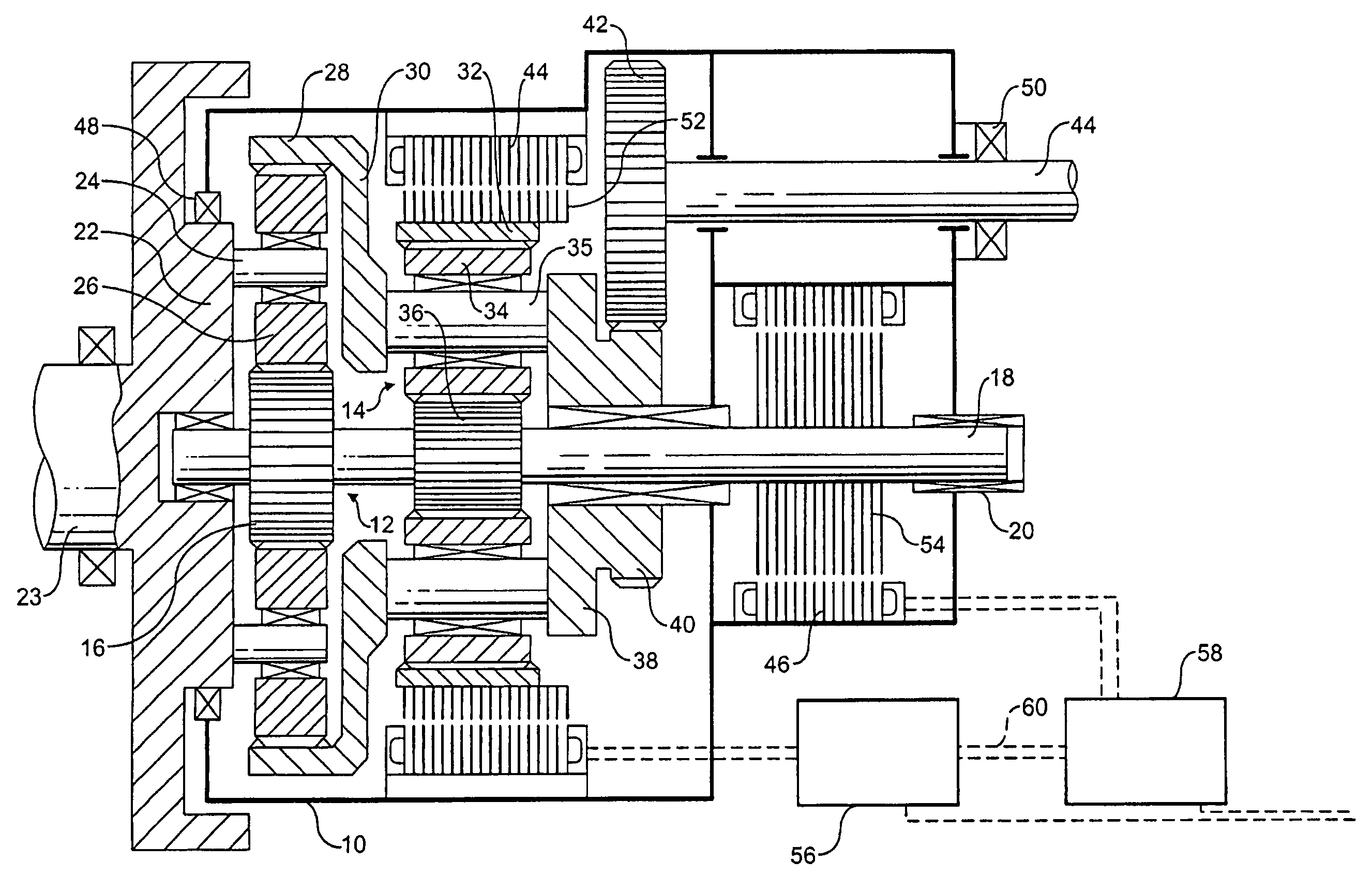
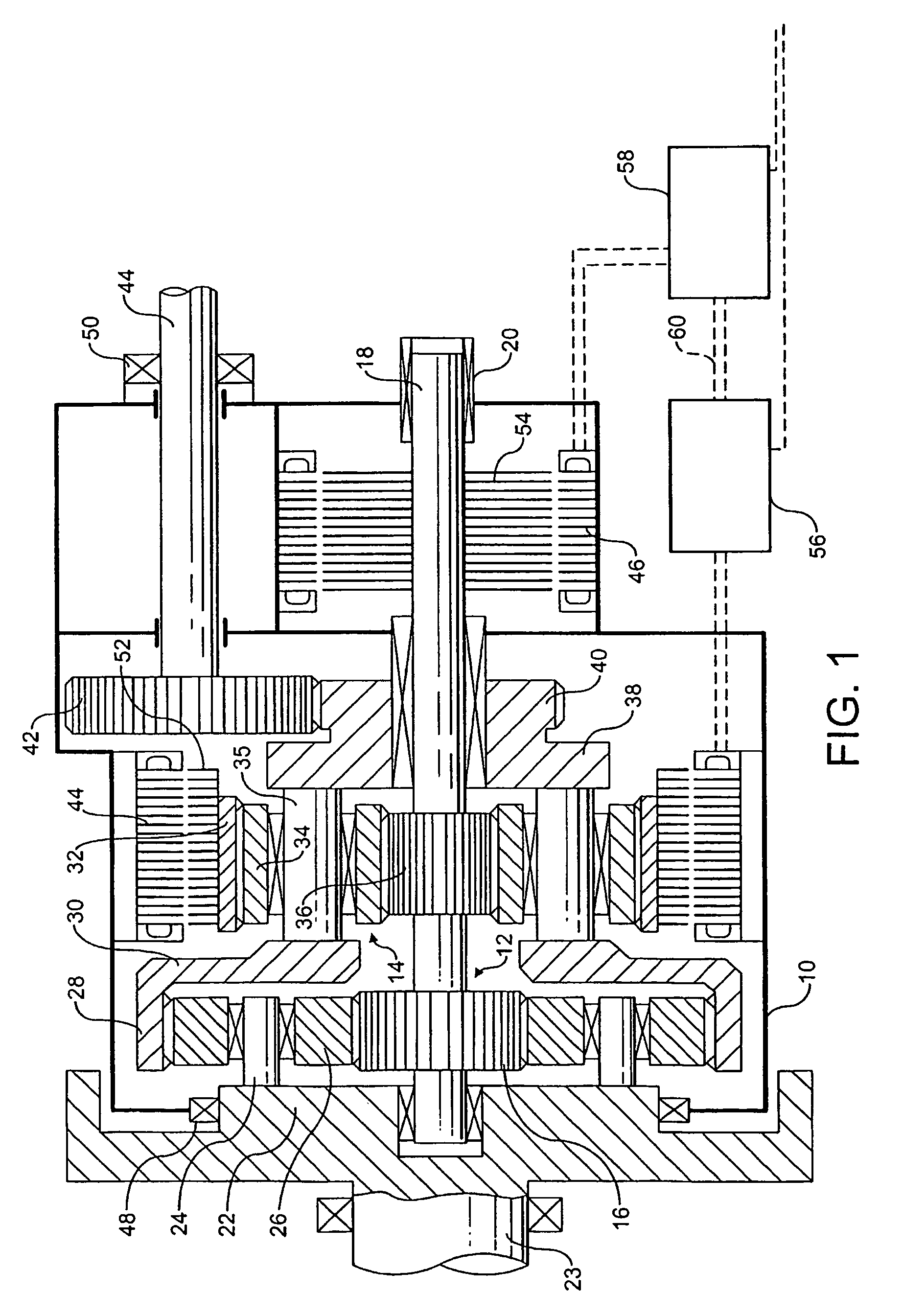
[0028]The transmission shown in FIG. 1 comprises an outer housing 10 accommodating two epicyclic gearsets 12 and 14. The first gearset 12 comprises a first sunwheel 16, which is fixedly carried by a shaft 18 which is mounted to rotate with respect to the housing 10 by bearings 20. A first carrier 22, which constitutes a flywheel and is connected to an input shaft 23 to the transmission carries a number, in this case three, of equispaced shafts 24, which carry respective first planet wheels 26. The first planet wheels 26 are in mesh with the first sunwheel 16 and with an internally toothed first annulus 28.

[0029]The first annulus 28 is connected via a radial flange 30 to shafts 35, of which there are three, which carry respective second planet wheels 34 and are connected to a second carrier 38. The planet wheels 34 are in mesh with internal toothing on the second annulus 32 and in mesh with a second sunwheel 36 fixedly carried by the shaft 18. The second carrier 38 includes an extern...


PUM


Abstract

An automotive vehicle transmission system has two epicyclic gearsets and a first and second electrically connected motor/generator. Components of the epicyclic gearsets and the motor/generators are connected such that, when the transmission system is in use, electrical power is transferred between the first and second motor/generators.

Description

[0001]This application is a national phase application based on PCT / GB02 / 05429, filed Dec. 4, 2002, the content of which is incorporated herein by reference and claims the priority of British Application No. 0129125.1, filed Dec. 5, 2001.BACKGROUND[0002]1. Field of the invention[0003]The present invention relates to automotive vehicle transmission systems and is concerned with that type of such system which comprises two or more compounded epicyclic gearsets, two elements of one of which are connected to rotate with respective elements of the other and connected to rotate with one element of each of which is a respective electric motor / generator unit, the electrical stator connections of which are connected together, whereby power is transferred between the two motor / generator units. Such a transmission system is referred to as of power split or torque split type because the power passing through it is transmitted in part mechanically, i.e. through the two mechanical connections, an...

Claims


Application Information

Patent Timeline
Patent Type & Authority Patents(United States)
IPC IPC(8): F16H3/72B60K1/02B60K6/26B60K6/365B60K6/40B60K6/445B60W10/08B60W10/10B60W20/00H02K7/116H02K16/00
CPCB60K6/365B60K6/40B60K6/445B60W10/08B60W10/10F16H3/727H02K7/116H02K16/00B60L3/0061B60L11/123B60L11/14B60L15/2054B60K6/26B60K1/02Y10T477/23B60L2240/486B60W20/00B60W2510/104F16H2037/102Y02T10/641Y02T10/6239B60L2240/12B60L2240/421B60L2240/423B60L2240/441B60L2260/26B60L2270/145Y02T10/72B60L50/61B60L50/16Y02T10/62Y02T10/64Y02T10/7072Y02T10/70B60W20/15
Inventor MOELLER, FRANK
Owner DRIVETEC (UK) LTD
Why Eureka
Try Eureka