Maritime overboard detection and tracking system

a tracking system and detection system technology, applied in the field of shipboard security systems, can solve the problems of relatively small objects, unsatisfactory solutions for solving the problem of people overboard, and high angular rate of chang

Inactive Publication Date: 2014-08-19
SECURITY IDENTIFICATION SYST
View PDF11 Cites 12 Cited by
  • Summary
  • Abstract
  • Description
  • Claims
  • Application Information

AI Technical Summary

Benefits of technology

[0007]A video system maps the external area beyond the hull of the ship, which area is displayed on a security monitoring control panel to identify the sensor and display the corresponding area where the object caused the alarm. The detection system activates a record of the time, date of sensor activation and initiates a system to acquire the Global Positioning Satellite (“GPS”) system coordinates. A video camera system positioned to view the area, over which the sensor constantly scans, records the area. When a person is detected, the camera system automatically videos the person and records the video, allowing the crew to playback the incident that caused the alarm and locate the position of the event. This same camera or a camera operating contemporaneously and in parallel permits the simultaneous panning of the area above and below the alarmed sensor to allow crew at the security console to view what occurred in real-time following the initiation of the alarm. Each camera has the functionality for a long range audio device option which allows the crew to communicate instructions to the person overboard. These instructions can be prerecorded and completely automated.

Problems solved by technology

Until now solving the person overboard problem had not yielded satisfactory solutions, in part because the sensors required to detect an event that occurred over a span of 180 degrees in close proximity to the sensor head and thereafter accompanied by the means to capture the event itself were unavailable.
A significant reason why a satisfactory solution has not been found is that the detection of a relatively small object (e.g., size of a baby) falling from a ship, relative to a sensing and detection mechanism, has a very high angular rate of change.

Method used


Image

  • Maritime overboard detection and tracking system
  • Maritime overboard detection and tracking system
  • Maritime overboard detection and tracking system

Examples


Embodiment Construction

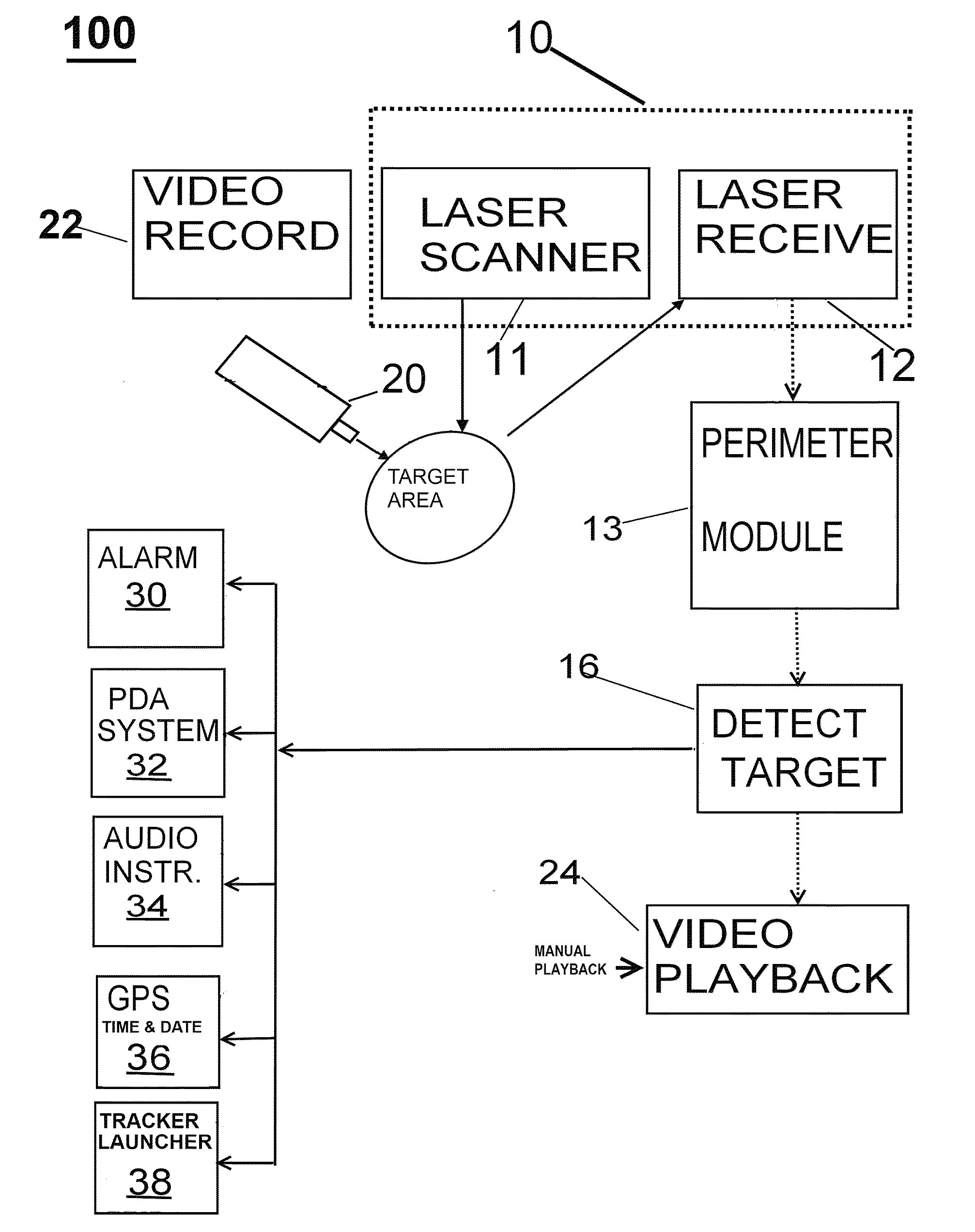
[0021]In the figures to be discussed, the circuits and associated blocks and arrows represent functions of the process according to the present invention, which may be implemented as electrical circuits and associated wires or data busses, which transport electrical signals. Alternatively, one or more associated arrows may represent communication (e.g., data flow) between software routines, particularly when the present process or apparatus of the present invention is a digital process. The invention described herein utilizes electronic processors, such as computers having data storage means, to process the data and perform mathematical computations using algorithms for accomplishing the stated goal: determination of an initial-track having sufficient predictive validity from one scan's worth of detection.

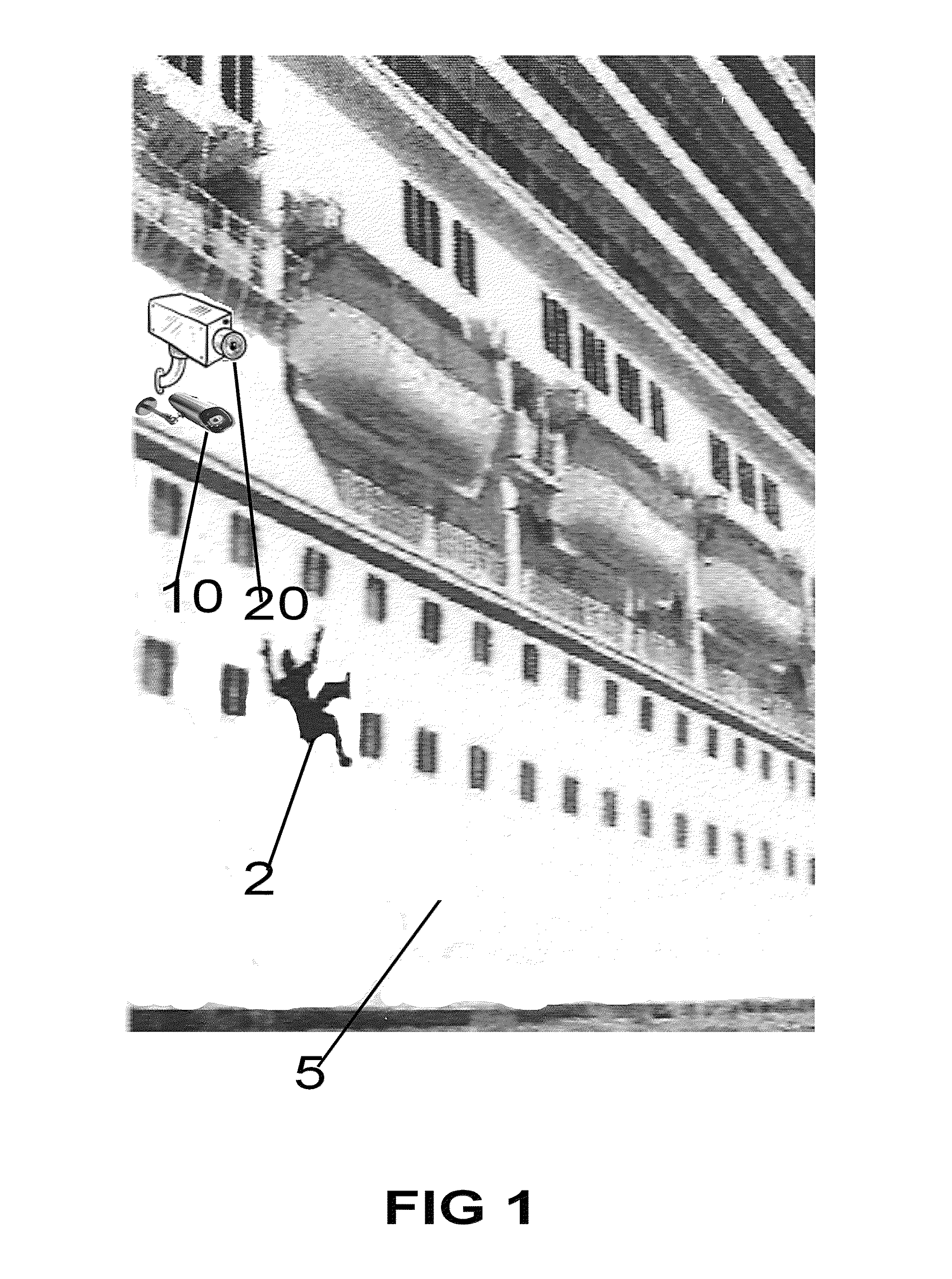
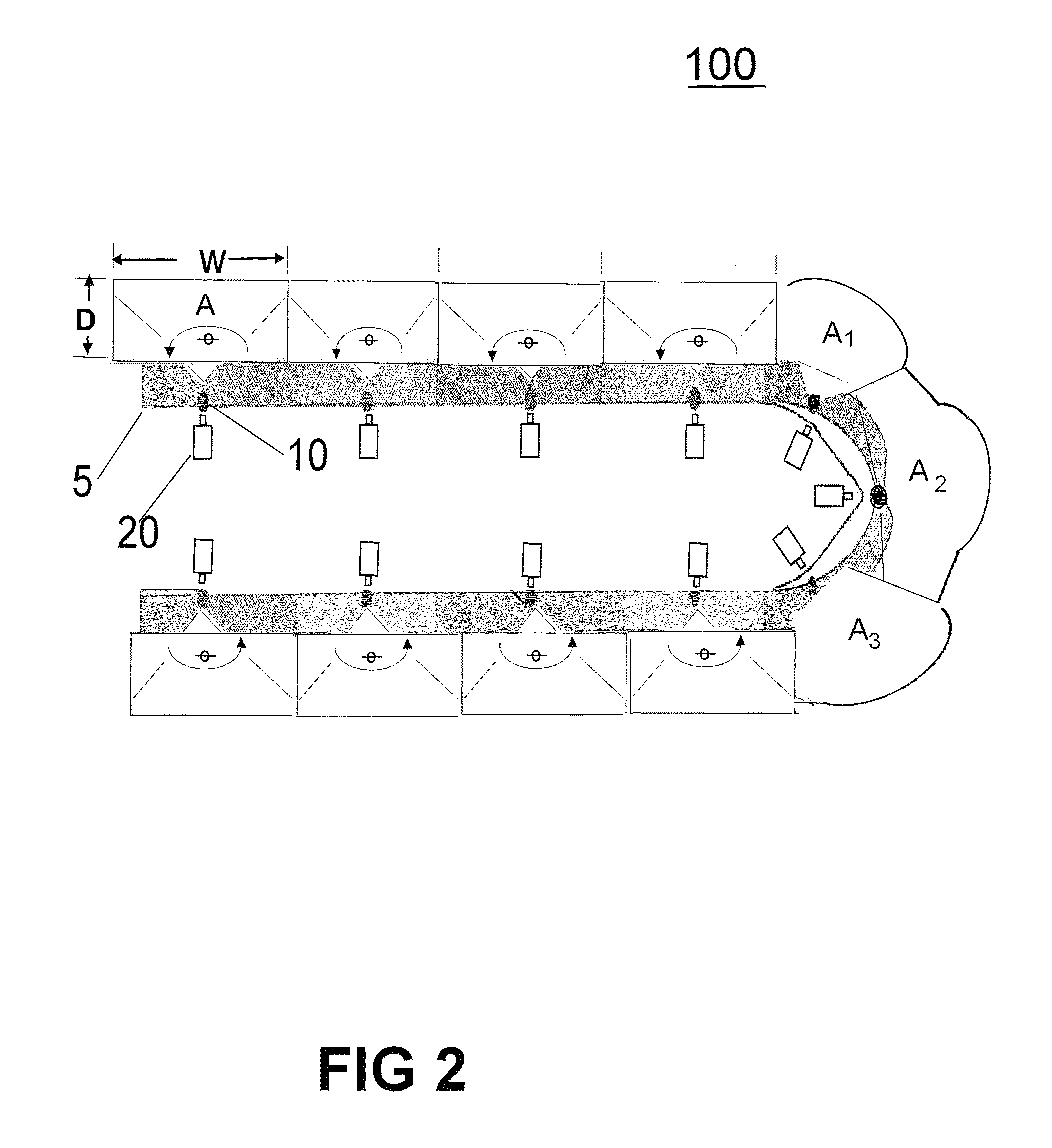
[0022]FIG. 2 shows the cross section of ship beneath the lowest deck (see FIG. 1), having one or more laser sensors 10 and associated one or more video camera systems 20 located in...


PUM


Abstract

A process and system for detecting the presence of a person overboard including: setting the perimeter of an area to scan, scanning the area 180 degrees in azimuth utilizing a laser beam for receiving a reflection of the laser beam off the person, detecting the reflection and playing back a video recording of the trajectory of the person, wherein the area above and below the perimeter of an area to scan is continuously video recorded and wherein upon detecting the target, one or more of audio and visual alarms alert that crew, and wherein an alarm with location is sent to PDA system with GPS coordinates time and date. Additionally a launcher deploys a device to track the person overboard, and allows persons on the ship or in a control center to ascertain the location of the person overboard.

Description

CROSS-REFERENCE TO RELATED APPLICATIONS[0001]The present application is related to, and incorporates by reference, the following application having the same assignee as the present application: US Patent Application Publication Number 2010-0282839, entitled “Method and System for the Mobile Tracking and Accounting of Individuals in a Closed Community,” having application Ser. No. 12 / 387,856, filed May 7, 2009 and seeks the benefit of the earlier filing date under 35 USC 120 provisional patent application entitled “Maritime Overboard Detection and Tracking System” having application Ser. No. 61 / 451,151, filed Mar. 10, 2011.FIELD OF THE INVENTION[0002]This application relates generally to shipboard security systems, and more particularly to alerting the crew in the event that a person falls overboard.BACKGROUND OF THE INVENTION[0003]This invention provides an apparatus, system and method for ship surveillance, detection and recording a person 2 overboard event as illustrated in FIG. 1...

Claims


Application Information

Patent Timeline
Patent Type & Authority Patents(United States)
IPC IPC(8): H04N7/18G08B23/00G08B13/183G08B13/196G01S17/02G01S17/04G01S17/86
CPCG08B13/183G01S17/023G01S17/026H04N7/18G08B13/19647G08B13/19697G08B21/086B63C9/0005G01S17/04G01S17/86
Inventor ZAGAMI, ANTHONYCARVALKO, JOSEPH
Owner SECURITY IDENTIFICATION SYST
Why Eureka
Try Eureka