Media device auto-detection
a technology of media devices and detection methods, applied in error detection/correction, instruments, stereophonic circuit arrangements, etc., can solve the problem of not teaching a solution to switch the source of audio content, and achieve the effect of reducing the impedance and lowering the coupling
- Summary
- Abstract
- Description
- Claims
- Application Information
AI Technical Summary
Benefits of technology
Problems solved by technology
Method used
Image


Examples
embodiment 10
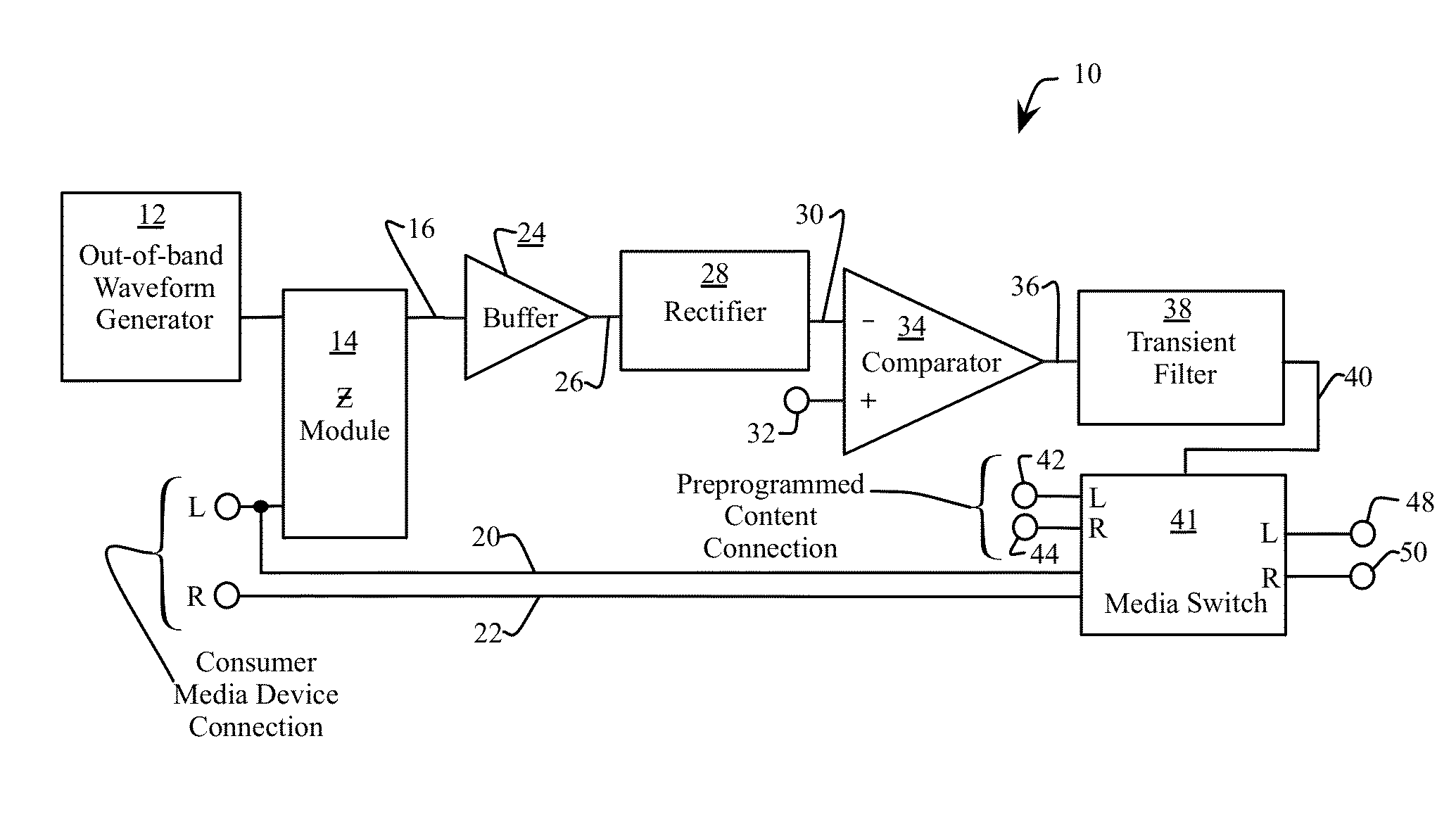
[0023]FIG. 1 illustrates an embodiment 10 of the functional blocks of the media device auto-detection system. An out-of-band waveform generator 12 generates a signal with substantially all of the frequency components being above the range of a media content generated by either a media source in the demonstration system or the consumer media device. Specifically, the fundamental frequency (e.g. first harmonic) of the generated waveform is above a maximum frequency of the frequency range of the media content. In one embodiment, the generated waveform is monotonic (e.g. a pure sinusoid). In another embodiment, the generated waveform is a damped square wave, shaped to remove lower frequencies that can mix with the media content and degrade the fidelity of the output of the demonstration system. In addition, the use of a higher frequency waveform from the waveform generator 12 substantially eliminates direct current (DC) signals from feeding back to the consumer media device and potentia...
embodiment 24
[0031]FIG. 3 shows an embodiment 24 of the buffer as shown in FIG. 1, used to isolate the impedance of the impedance module 14 from the rectifier 28. The buffer 24 includes an operational amplifier (op-amp) 82 with an output 26. A feedback resistor 86 connects the output 26 to the negative input 88 of the op-amp 82. A resistor 90 is connected between the negative input 88 and a ground 92. The ratio of the resistor 86 and the resistor 90 establishes the gain or amplification of the buffer 24. In a preferred embodiment, resistors 86 and 90 are 9.09 KΩ and 10 KΩ respectively, thus providing a slight attenuation of the output 16 of the impedance module 14. In another embodiment, the buffer 24 is a simple voltage follower with no attenuation. In another embodiment, the buffer 24 amplifies the output 16. A resistor 94 is connected between the supply voltage 96 and the output 16. A resistor 98 is connected between the output 16 and the ground 92. The output 16 connects to a positive input ...
PUM
 Abstract
Description
Claims
Application Information