RFID system

a radio frequency identification and tag technology, applied in the direction of burglar alarm mechanical actuation, burglar alarm by hand-held articles removal, instruments, etc., can solve the problems of poor performance of a tag directly on a metallic surface, poor performance of a tag, and inability to operate satisfactorily

Active Publication Date: 2014-08-26
PANDUIT
View PDF87 Cites 44 Cited by
  • Summary
  • Abstract
  • Description
  • Claims
  • Application Information

AI Technical Summary

Problems solved by technology

Nevertheless, the bar code methods are manually implemented, and therefore have cost and accuracy issues, notwithstanding that they are certainly better than processes that are completely manual.
Since the IT equipment RFID tags are typically mounted on metallic surfaces, such as surface 155 shown in FIG. 1d, the performance of a tag directly on a metallic surface will be poor unless special design considerations are applied.
If the tag is placed outside of this region, the tag may not operate satisfactorily.

Method used


Image

  • RFID system
  • RFID system
  • RFID system

Examples


Embodiment Construction

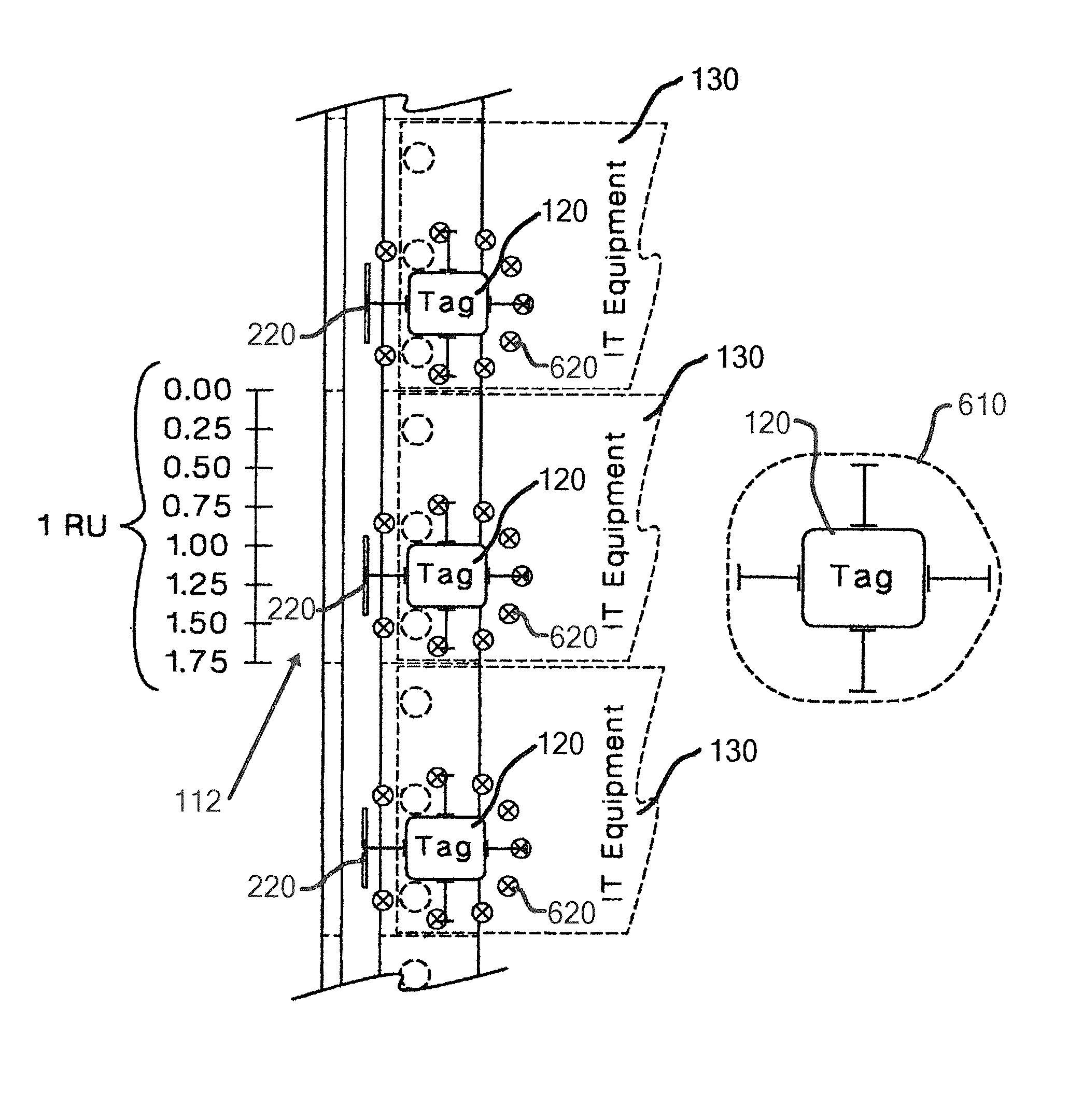
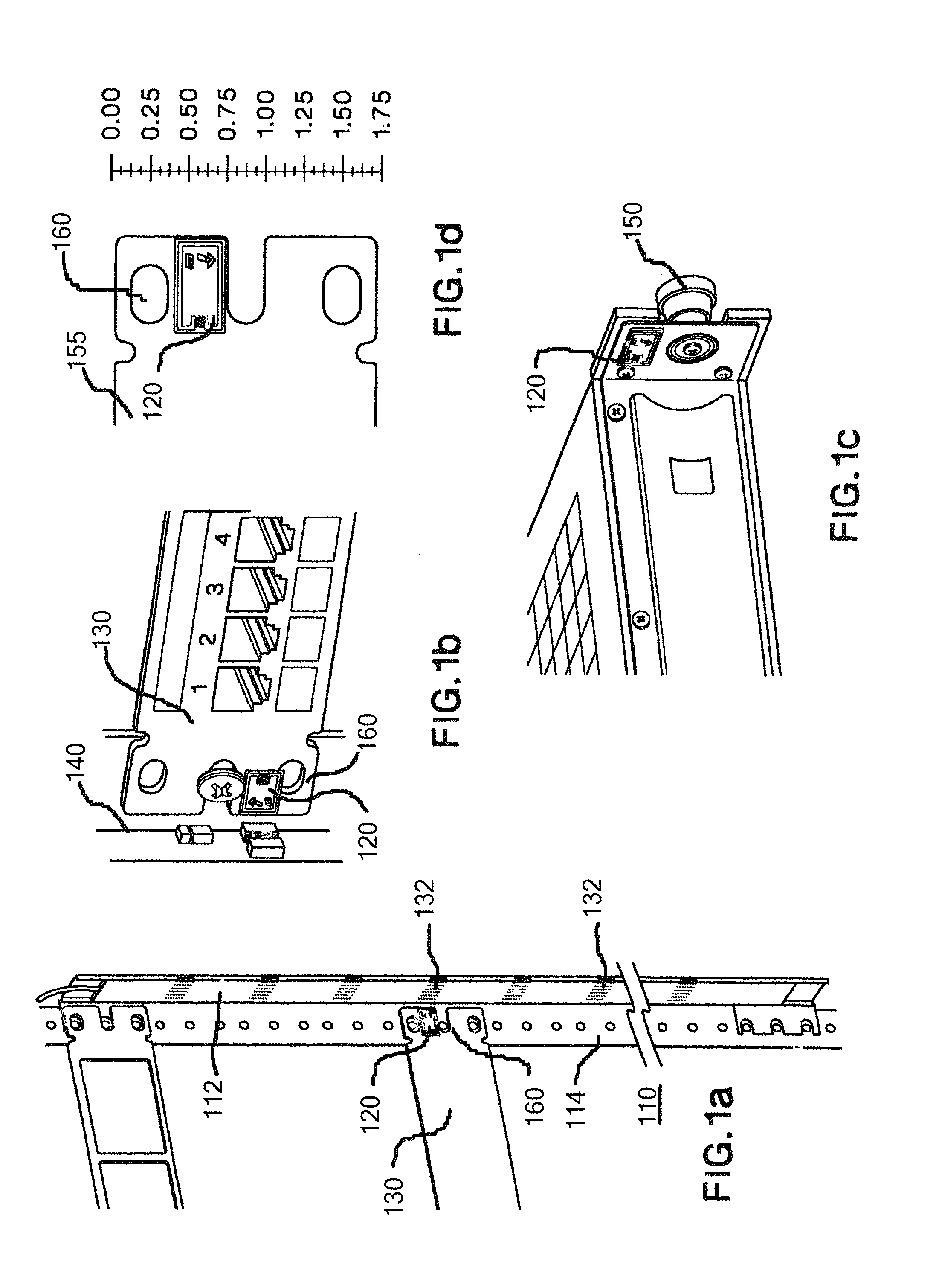
[0025]With reference to FIGS. 1a to 1d, simplified isometric and plan representations of a specific illustrative embodiment of the invention are depicted along with an illustrative asset tracking system. FIG. 1a illustrates the use of RFID at the rack unit level of granularity. More specifically, RFID tagged equipment is illustrated in use with a rack unit 110.

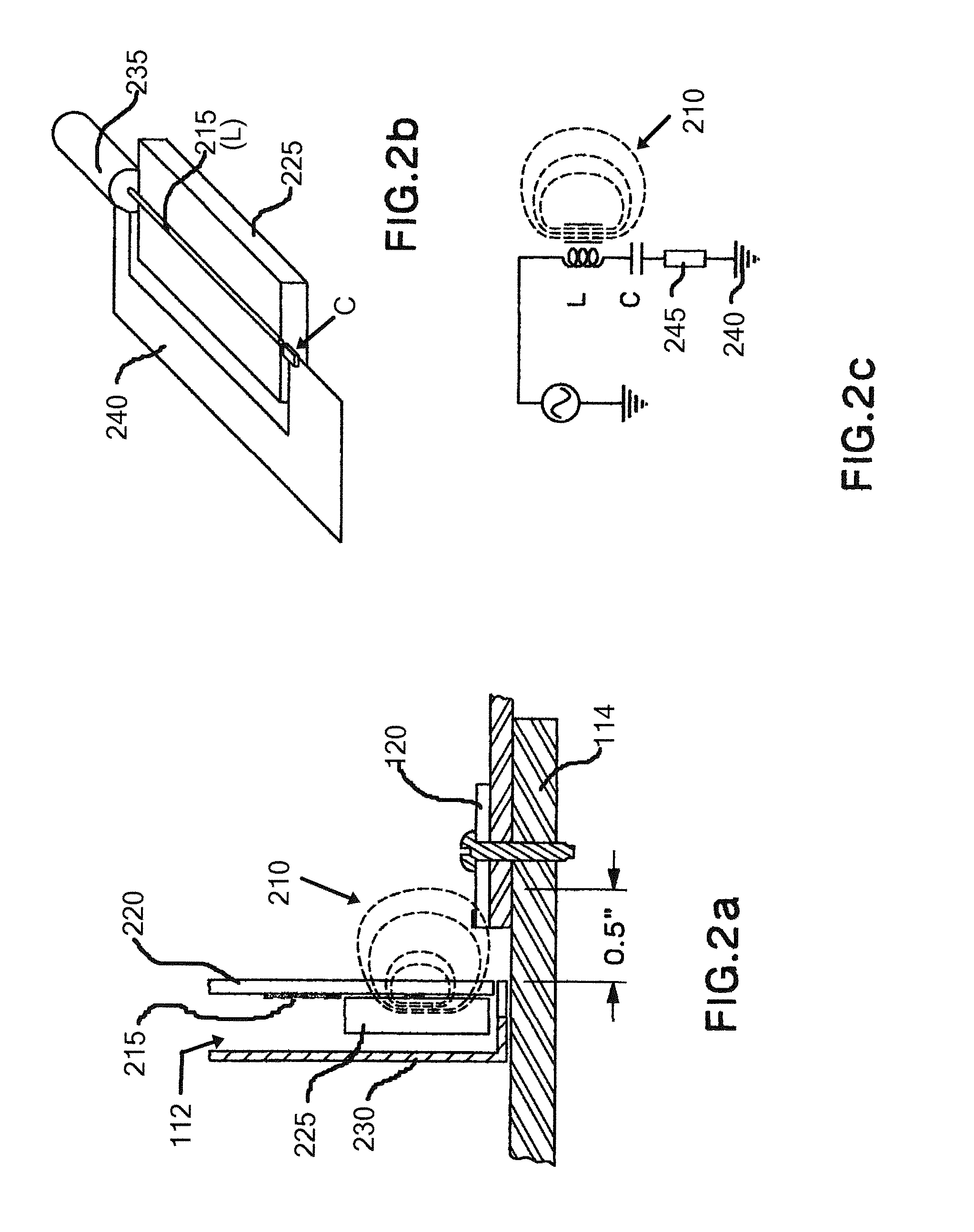
[0026]The technique of the present invention relies on near field magnetic coupling between an antenna array 112 mounted on the rack's mounting post 114 and an RFID tag 120 that is installed on RFID tagged equipment 130. Referring to FIG. 1b, there is shown in isometric representation RFID tag 120 that is attached to IT equipment 130 that mounts in the rack. FIGS. 1a through 1d illustrate two key components of the RFID rack-unit-based asset tracking management system of the present invention, specifically antenna array 112 and RFID tag 120 attached to the IT equipment. Antenna array 112, which as stated is mounted onto the rac...


PUM


Abstract

The present invention provides an automated system for asset tracking and management and utilizes near field Radio Frequency IDentification (RFID) technology. RFID tags are attached to the assets, and RFID antennas (and corresponding readers) are strategically located in close proximity to read the tags. As applied to a rack or cabinet, near-field antennas are mounted along one of the mounting posts at each rack unit location such that when a piece of equipment (rack mounted or rail mounted) is installed at a particular rack unit space, the tag will be read and registered in an RFID management system. A magnetic field shaping arrangement ensures that crosstalk between adjacent rack positions is prevented. Ferrite elements are used to control the magnetic field.

Description

CROSS-REFERENCE TO RELATED APPLICATION[0001]This application claims priority to U.S. Provisional Application No. 61 / 394,924, filed Oct. 20, 2010, the subject matter of which is hereby incorporated by reference in its entirety.BACKGROUND[0002]This invention relates generally to asset tracking systems, and more particularly to Radio Frequency IDentification (RFID) systems that employ ferrite material to shape the magnetic field pattern of an antenna-like source or detector[0003]Asset tracking within Data Centers is important for the assistance in inventory audits, physical location identification of assets that require repair or de-commissioning, and for rack environmental management. The industry currently addresses this problem largely by the implementation of manual techniques (handwritten or Excel® spreadsheet-based physical location of assets). Some data center managers have improved upon these techniques by incorporating barcode systems into their asset tracking methods. Neverth...

Claims


Application Information

Patent Timeline
Patent Type & Authority Patents(United States)
IPC IPC(8): G08B13/14G06K7/00G06K17/00G06K19/077
CPCG06K19/07749G06K7/0008G06K7/10168G06K19/07771G06K2017/0051G06K7/10356G06Q10/087G06K7/10336
Inventor NORDIN, RONALD A.BOLOURI-SARANSAR, MASUD
Owner PANDUIT
Why Eureka
Try Eureka